
Projection data acquisition apparatus

a technology of projection data and acquisition apparatus, which is applied in the field of projection data acquisition apparatus, method and computer program, and can solve problems such as increasing nois

Active Publication Date: 2019-10-15
KONINKLJIJKE PHILIPS NV
View PDF21 Cites 1 Cited by
  • Summary
  • Abstract
  • Description
  • Claims
  • Application Information

AI Technical Summary

Benefits of technology

The present invention provides a projection data acquisition apparatus, method, and computer program for acquiring high-quality computed tomography images. The apparatus includes a collimator that partially blocks the radiation beam to create a shadowed region and a non-shadowed region, and a correction unit that uses the scatter data to improve the quality of the projection data. The collimator can be rotated to generate different shapes of the pulsed radiation beam at different acquisition positions. The apparatus also includes a radiation dose constraints providing unit to ensure that the radiation dose applied to the object is not too high. The moving unit is adapted to move the radiation device relative to the object along an acquisition trajectory to sparsely sample the projection data and reduce the radiation dose.

Problems solved by technology

Using these smaller pulsed radiation beams at least at certain acquisition positions leads to less scattered radiation, wherein generally scattered radiation does not only generate image artifacts, but also increases the noise.

Method used


Image

  • Projection data acquisition apparatus
  • Projection data acquisition apparatus
  • Projection data acquisition apparatus

Examples


Embodiment Construction

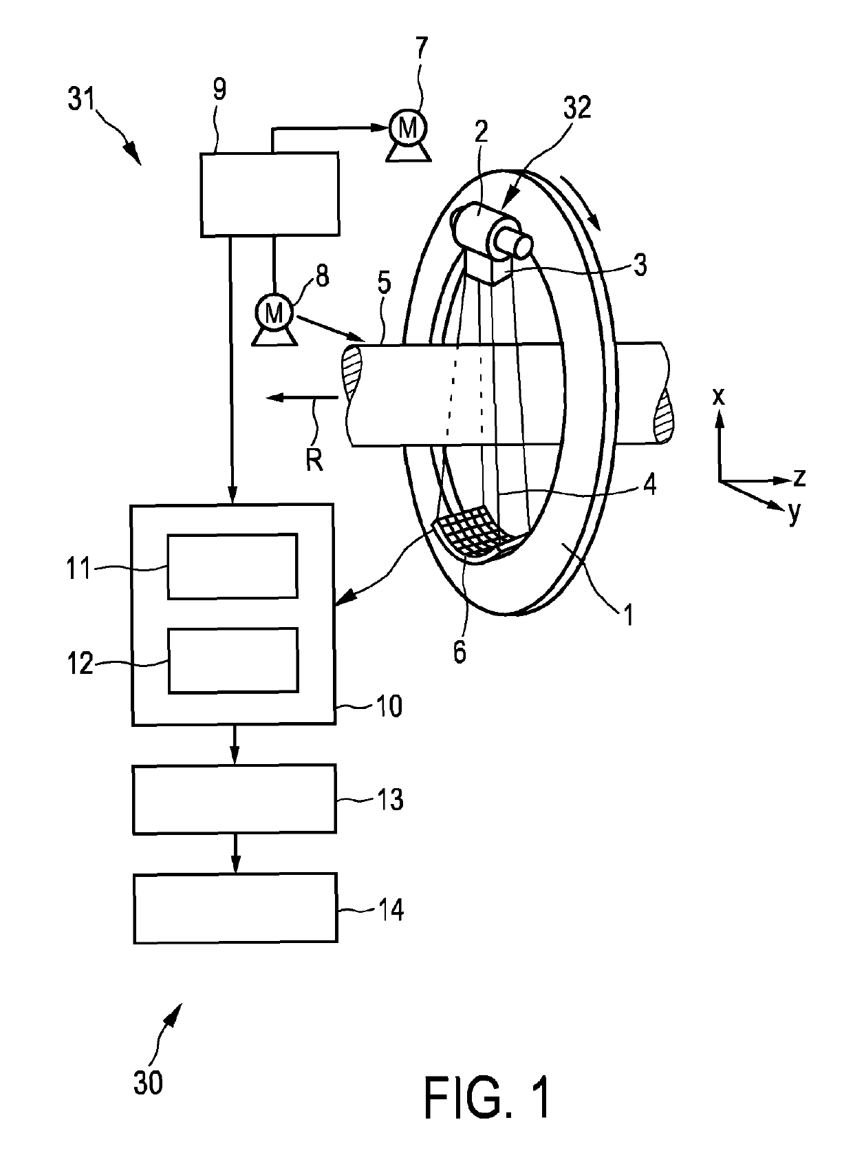
[0042]FIG. 1 shows schematically and exemplarily an embodiment of a computed tomography system for generating a computed tomography image of an object. The computed tomography system 30 includes a gantry 1 which is capable of rotation about a rotational axis R which extends parallel to a z axis. A radiation device 32 is mounted on the gantry 1. The radiation device 32 comprises a radiation source 2 for generating a pulsed radiation beam 4 and a collimator 3 for shaping the generated pulsed radiation beam 4. In particular, the collimator 3 is adapted to partially block the pulsed radiation beam 4 for shaping the pulsed radiation beam 4. The radiation source 2 is preferentially a grid switching x-ray source.

[0043]The radiation 4 traverses an object (not shown), such as a person, in an examination zone 5 being, in this embodiment, cylindrical. After having traversed the examination zone 5 and thus the object within the examination zone 5 the radiation beam 4 is incident on a detection ...


PUM

PropertyMeasurementUnit
thicknessaaaaaaaaaa
diameteraaaaaaaaaa
rotation timeaaaaaaaaaa

Abstract

The invention relates to a projection data acquisition apparatus (31) for acquiring projection data. The projection data acquisition apparatus comprises a radiation device (32) for generating a pulsed radiation beam (4) for traversing an object and a detection device (6) for generating projection data being indicative of the pulsed radiation beam (4) at different acquisition positions, wherein the radiation device (32) is adapted to generate the pulsed radiation beam (4) such that at different acquisition positions the pulsed radiation beam (4) has different shapes, i.e. is differently blocked and / or attenuated. Thus, not the complete radiation providable by the radiation device is used at each acquisition position, but at least at some acquisition positions only a smaller pulsed radiation beam is used. This can lead to less scattered radiation and hence to improved projection data and an improved computed tomography image, which may be reconstructed based on the acquired projection data.

Description

CROSS REFERENCE TO RELATED APPLICATIONS[0001]This application is the U.S. National Phase application under 35 U.S.C. § 371 of International Application No. PCT / EP2015 / 065993, filed Jul. 13, 2015, published as WO 2016 / 008856 on Jan. 21, 2016, which claims the benefit of European Patent Application Number 14176988.5 filed Jul. 15, 2014. These applications are hereby incorporated by reference herein.FIELD OF THE INVENTION[0002]The invention relates to a projection data acquisition apparatus, method and computer program for acquiring projection data. The invention relates further to a collimator, which may be used by the projection data acquisition apparatus, a computed tomography system comprising the projection data acquisition apparatus and a corresponding computed tomography method and computer program.BACKGROUND OF THE INVENTION[0003]A computed tomography system comprises a radiation device for generating a radiation beam for traversing an object, a detection device for generating ...

Claims


Application Information

Patent Timeline
Patent Type & Authority Patents(United States)
IPC IPC(8): A61B6/00A61B6/06A61B6/03G01N23/046
CPCA61B6/032A61B6/06A61B6/405A61B6/4429A61B6/5282A61B6/542G01N23/046
Inventor PROKSA, ROLANDGRASS, MICHAEL
Owner KONINKLJIJKE PHILIPS NV
Learn More