Ejector refrigeration cycle device and low outside temperature operation thereof

a technology of ejector and refrigeration cycle, which is applied in the direction of refrigeration components, subcoolers, lighting and heating apparatus, etc., can solve the problem of not being able to cool a cooling target fluid by the evaporator, and achieve the reduction of the suction capacity of the ejector, and the reduction of the flow rate and flow velocity of the injection refrigeran

Active Publication Date: 2019-10-15
DENSO CORP
View PDF13 Cites 0 Cited by
  • Summary
  • Abstract
  • Description
  • Claims
  • Application Information

AI Technical Summary

Benefits of technology

[0009]As mentioned above, the ejector draws the refrigerant by the suction effect of the injection refrigerant. For this reason, if the flow rate and flow velocity of the injection refrigerant are decreased, a suction capacity of the ejector for drawing the refrigerant from the outlet side of the evaporator might be reduced. Thus, for example, in the ejector refrigeration cycle device applied to the air conditioner, the suction capacity of the ejector is reduced on an operating condition in which a thermal load of the cycle is relatively low, like a dehumidification heating operation executed at a low outside-air temperature.

Problems solved by technology

For this reason, the refrigerant cannot flow into the evaporator at the low outside-air temperature, which might make it impossible to cool a cooling target fluid by the evaporator.

Method used


Image

  • Ejector refrigeration cycle device and low outside temperature operation thereof
  • Ejector refrigeration cycle device and low outside temperature operation thereof
  • Ejector refrigeration cycle device and low outside temperature operation thereof

Examples


first embodiment

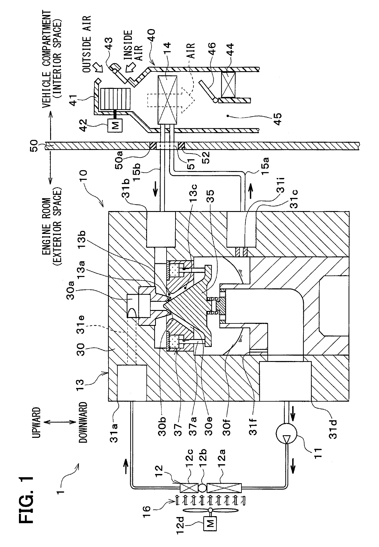
[0032]A first embodiment of the present disclosure will be described below with reference to FIGS. 1 to 6. As shown in the entire configuration diagram of FIG. 1, an ejector refrigeration cycle device 10 in this embodiment is applied to a vehicle air conditioner 1 and serves to cool ventilation air to be blown into a vehicle interior as a space to be air-conditioned (interior space). Thus, a fluid to be cooled by the ejector refrigeration cycle device 10 is the ventilation air.

[0033]The ejector refrigeration cycle device 10 forms a subcritical refrigeration cycle in which a high-pressure side refrigerant pressure does not exceed the critical pressure of the refrigerant, using a hydrofluorocarbon (HFC)-based refrigerant (e.g., R134a) as the refrigerant. Obviously, a hydrofluoroolefin (HFO)-based refrigerant (e.g., R1234yf) or the like may also be adopted as the refrigerant. Further, refrigerating machine oil for lubricating a compressor 11 is mixed into the refrigerant, and part of t...

second embodiment

[0140]In this embodiment, as shown in the entire configuration diagram of FIG. 7, the grille shutter 16 is abolished, while a bypass passage 17a and an on / off valve 17b are provided by way of example, compared to the first embodiment. The bypass passage 17a serves to cause the high-pressure refrigerant discharged from the compressor 11 to bypass the radiator 12 and then to guide the refrigerant to the refrigerant inflow port 31a side of the ejector module 13. The on / off valve 17b serves to open and close the bypass passage 17a.

[0141]In more detail, when the on / off valve 17b opens the bypass passage 17a, the ejector refrigeration cycle device 10 in this embodiment can guide the high-pressure gas-phase refrigerant discharged from the compressor 11 to the downstream side of the radiator 12 as indicated by a dashed arrow in FIG. 7. Then, the high-pressure gas-phase refrigerant is mixed into the subcooled liquid-phase refrigerant flowing out of the radiator 12, which can increase the en...


PUM


Abstract

An ejector refrigeration cycle device includes: a radiator that dissipates heat from a refrigerant discharged from a compressor; an ejector module that decompresses the refrigerant cooled by the radiator; and an evaporator that evaporates a liquid-phase refrigerant separated in a gas-liquid separation space of the ejector module. A grille shutter is disposed as an inflow-pressure increasing portion between the radiator and a cooling fan blowing the outside air toward the radiator. The grille shutter is operated to decrease the volume of the outside air to be blown toward the radiator when an outside air temperature is equal to or lower than a reference outside air temperature, thereby increasing the pressure of the inflow refrigerant to flow into a nozzle passage of the ejector module.

Description

CROSS REFERENCE TO RELATED APPLICATIONS[0001]This application is a U.S. National Phase Application under 35 U.S.C. 371 of International Application No. PCT / JP2015 / 004095 filed on Aug. 18, 2015 and published in Japanese as WO 2016 / 063443 A1 on Apr. 28, 2016. This application is based on and claims the benefit of priority from Japanese Patent Application No. 2014-217457 filed on Oct. 24, 2014. The entire disclosures of all of the above applications are incorporated herein by reference.FIELD OF THE INVENTION[0002]The present disclosure relates to an ejector refrigeration cycle device that includes an ejector serving as a refrigerant decompression portion.BACKGROUND ART[0003]Conventionally, an ejector refrigeration cycle device is known to be a vapor compression refrigeration cycle device including an ejector as a refrigerant decompression portion.[0004]In this kind of ejector, a high-pressure refrigerant is isentropically decompressed by and injected from a nozzle portion. By the sucti...

Claims


Application Information

Patent Timeline
Patent Type & Authority Patents(United States)
IPC IPC(8): B60H1/32F25B41/06F25B41/00F25B27/00F25B49/02F25B40/02
CPCF25B27/00F25B40/02F25B41/00F25B49/02F25B2327/001F25B2341/0012F25B2341/0014F25B2400/0403F25B2400/0417F25B2400/121F25B2400/23F25B2500/18F25B2600/2501F25B2700/1931F25B2700/2104F25B2700/2106F25B2700/2117B60H2001/3298F25B41/335B60H1/3211B60H2001/3255B60H2001/3277B60H2001/3285
Inventor TASHIRO, TOSHIYUKIYAMADA, MASAHIROKUME, MAKOTONISHIJIMA, HARUYUKINAGANO, YOUHEIYOKOYAMA, YOSHIYUKIARAKI, YOSHINORI
Owner DENSO CORP
Why Eureka
Try Eureka