
Positioning device for shaped charges in a perforating gun module

a technology of perforating gun and shaped charge, which is applied in the direction of fluid removal, survey, borehole/well accessories, etc., can solve the problems of increasing the length of each perforating gun, reducing/limiting the size of explosive charges, and affecting the quality of the perforating gun

Active Publication Date: 2019-10-29
DYNAENERGETICS
View PDF76 Cites 67 Cited by
  • Summary
  • Abstract
  • Description
  • Claims
  • Application Information

AI Technical Summary

Benefits of technology

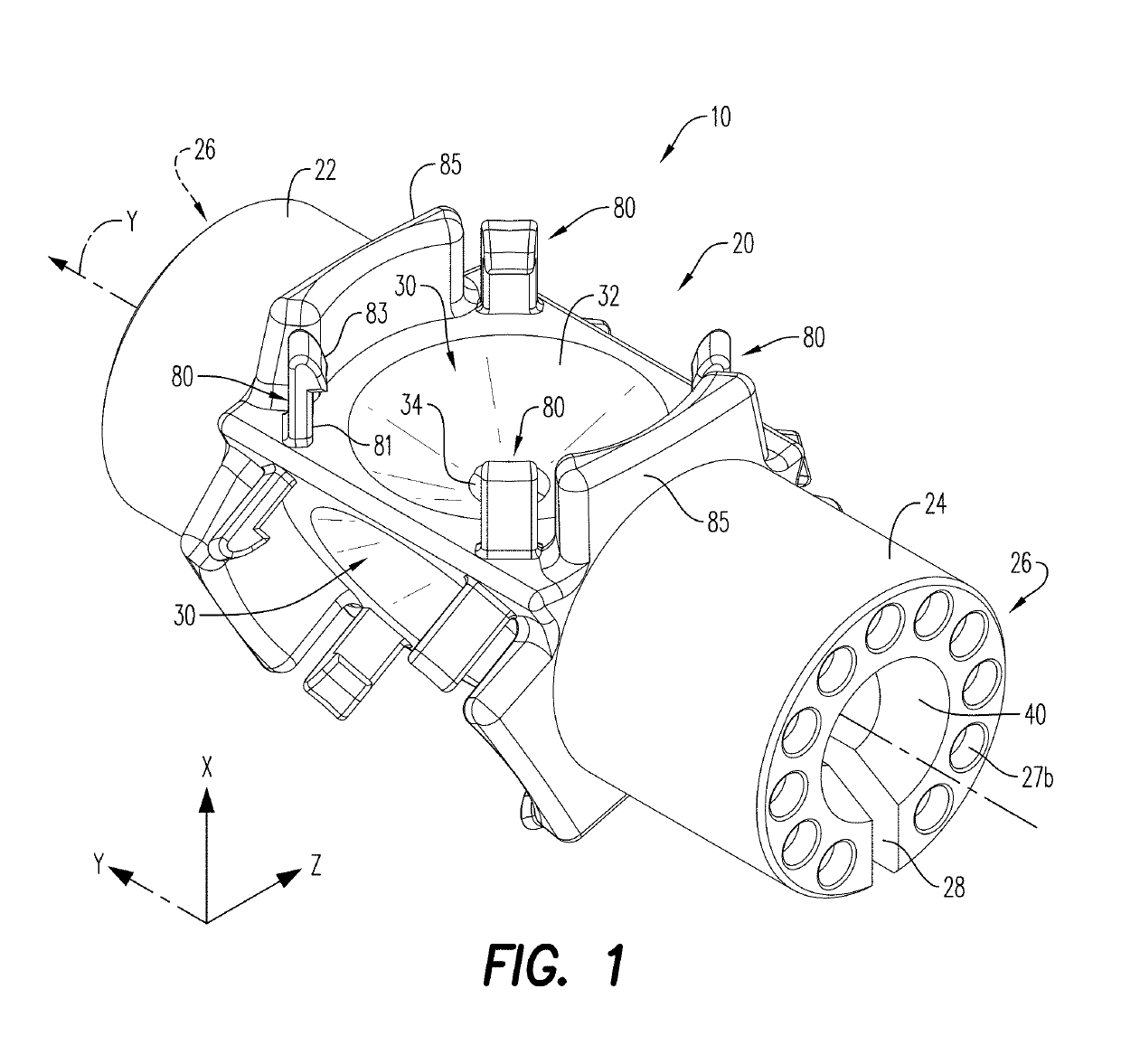
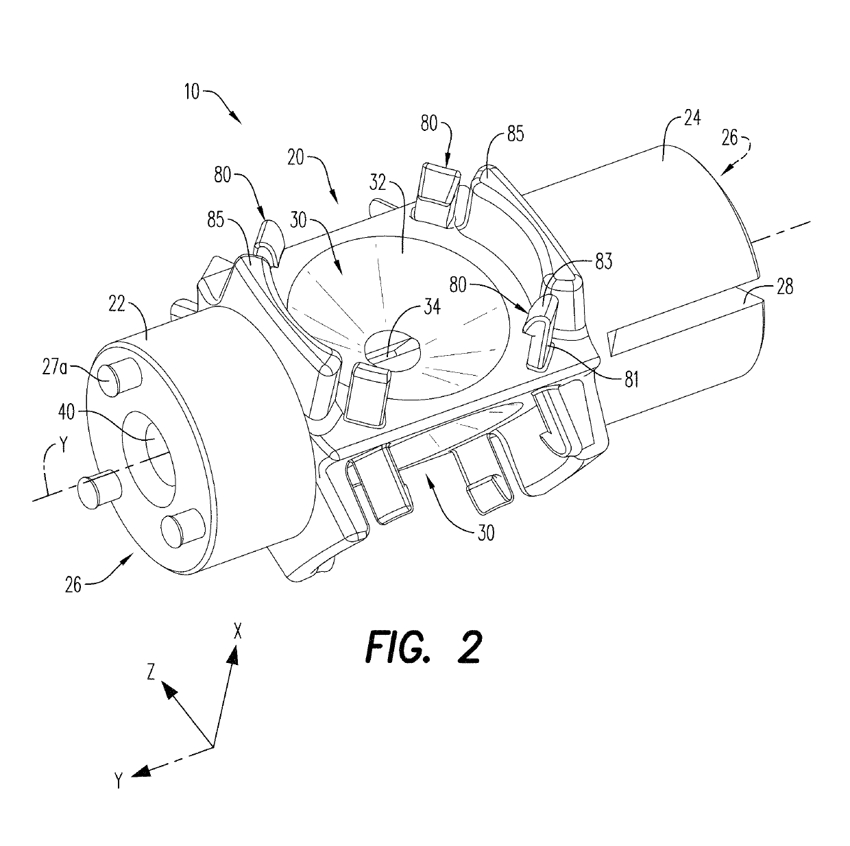
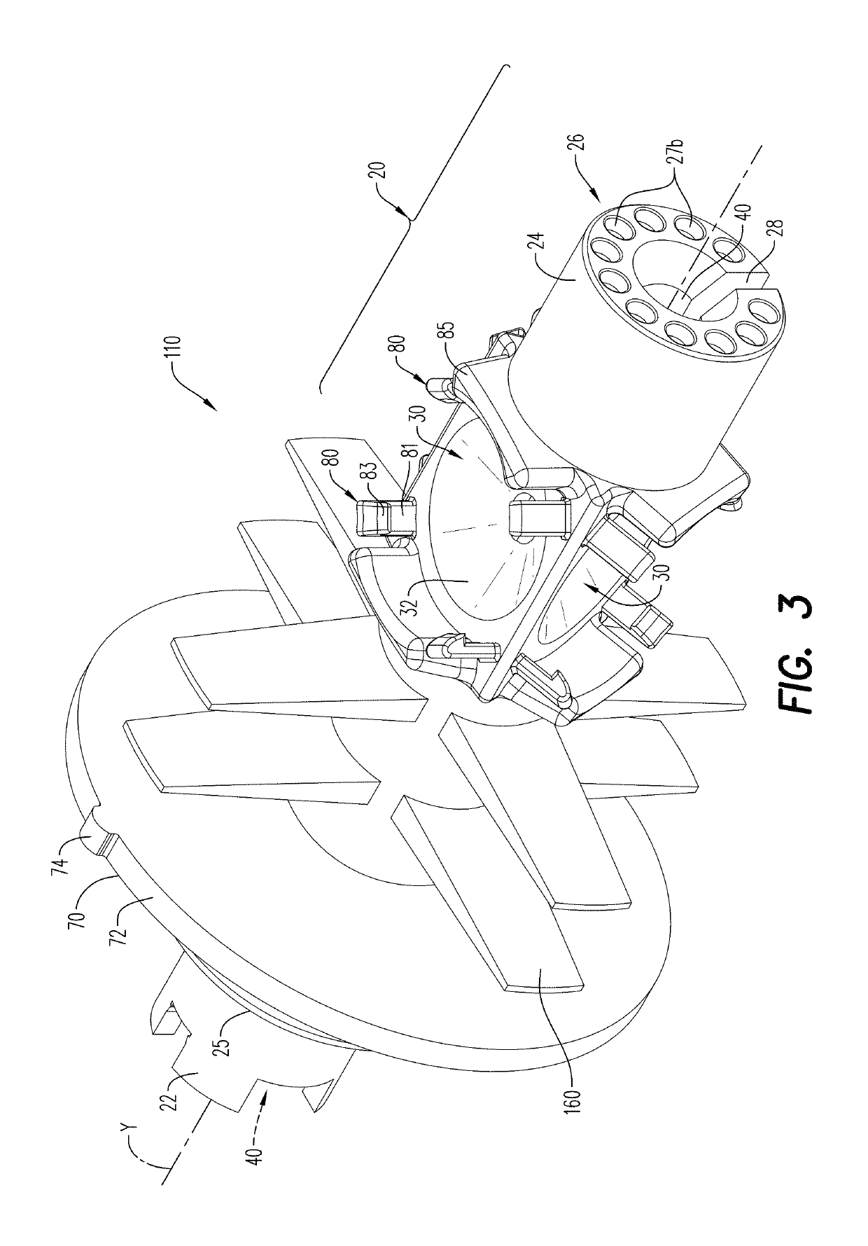
The patent text describes a positioning device for a shaped charge holder in a perforating gun module. The device includes a shaped charge holder with shaped charges arranged in an XZ-plane and an elongated cavity containing a detonator. The detonator is a wireless detonator that directly initiates the shaped charges. The positioning device also includes at least one rib to prevent movement of the shaped charges in the perforating gun module. The shaped charges create a perforating jet that has a geometry that facilitates a flow rate or hydraulic fracturing that is equivalent to the flow rate of another shaped charge of different size or composition. The positioning device may also include a deto-initator in the elongated cavity of the shaped charge holder. The perforating gun module includes a housing with a chamber for positioning the device and may also include at least one rib to capture the resulting mass created by the activation of the shaped charges. The technical effects of the patent text include improved accuracy in positioning the shaped charges and minimization of debris after detonation.

Problems solved by technology

Some tandem seal adapters may be provided internally or externally between adjacent perforating guns, which, in addition to requiring the use of multiple parts or connections between the perforating guns, may increase the length of each perforating gun and may be more expensive to manufacture.
Such debris may include shrapnel resulting from the detonation of the explosive charges, which may result in obstructions in the wellbore.
Such perforating gun assemblies require numerous components, may be costly to manufacture and assemble, and may reduce / limit the size of the explosive charges, in relation to the gun diameter, which may be compatible with the gun assembly.

Method used


Image

  • Positioning device for shaped charges in a perforating gun module
  • Positioning device for shaped charges in a perforating gun module
  • Positioning device for shaped charges in a perforating gun module

Examples


examples

[0090]Various perforating gun assemblies, including positioning devices and shaped charges, were made and tested, according to the embodiments of the disclosure. The shaped charges where detonated, and the total average shot area entrance hole diameters presented in the examples shown in Table 1 are based on the minimum and maximum hole diameter formed by the perforation jet upon detonation of the shaped charges.

[0091]

TABLE 1Shaped ChargeShot Count / Total Average ShotDiameter / CaliperQuantity ofArea of PerforationsSample(inches)Shaped Charges(square inches (in2))A-10.35 + / − 0.0320.19A-20.30 + / − 0.0330.21B-10.35 + / − 0.0330.29B-20.35 + / − 0.0330.29C-10.35 + / − 0.0340.38C-20.40 + / − 0.0430.38D-10.35 + / − 0.0350.48D-20.45 + / − 0.0530.48E-10.35 + / − 0.0360.58E-20.50 + / − 0.0530.59

[0092]The shaped charges tested (the results of the tests being presented in Table 1), each included a substantially cylindrical / conical case, an explosive load contained in a cavity of the case, and a liner disposed adj...


PUM


Abstract

A positioning device includes a shaped charge holder. A plurality of shaped charge receptacles formed in the shaped charge holder are configured to arrange a plurality of shaped charges in a desired orientation. The shaped charges are detonated by a detonator in response to an initiation signal. The positioning device may be secured in a perforating gun module, with vertical and horizontal movement of the positioning being inhibited in the perforating gun module.

Description

CROSS-REFERENCE TO RELATED APPLICATIONS[0001]The present application claims the benefit of U.S. Provisional Application No. 62 / 699,484 filed Jul. 17, 2018 and U.S. Provisional Application No. 62 / 780,427 filed Dec. 17, 2018, each of which is incorporated herein by reference in its entirety.BACKGROUND OF THE DISCLOSURE[0002]Hydrocarbons, such as fossil fuels (e.g. oil) and natural gas, are extracted from underground wellbores extending deeply below the surface using complex machinery and explosive devices. Once the wellbore is established by placement of casing pipes after drilling, a perforating gun assembly, or train or string of multiple perforating gun assemblies, are lowered into the wellbore, and positioned adjacent one or more hydrocarbon reservoirs in underground formations.[0003]Assembly of a perforating gun requires assembly of multiple parts. Such parts typically include a housing or outer gun barrel. An electrical wire for communicating from the surface to initiate ignitio...

Claims


Application Information

Patent Timeline
Patent Type & Authority Patents(United States)
IPC IPC(8): E21B43/1185E21B33/068E21B47/09
CPCE21B43/1185E21B33/068E21B47/09E21B43/117E21B43/119
Inventor EITSCHBERGER, CHRISTIANSHAHINPOUR, ARASHBURMEISTER, GERNOT UWESCHARF, THILO
Owner DYNAENERGETICS
Learn More