Discharge cap and block for a fluid end assembly

Active Publication Date: 2019-11-05
VP SALES & COMPANY
View PDF10 Cites 12 Cited by
  • Summary
  • Abstract
  • Description
  • Claims
  • Application Information

AI Technical Summary

Benefits of technology

[0018]The inventive discharge cover is tapered, leading to elimination of sharp edges in the fluid end. Further, the first and secon

Problems solved by technology

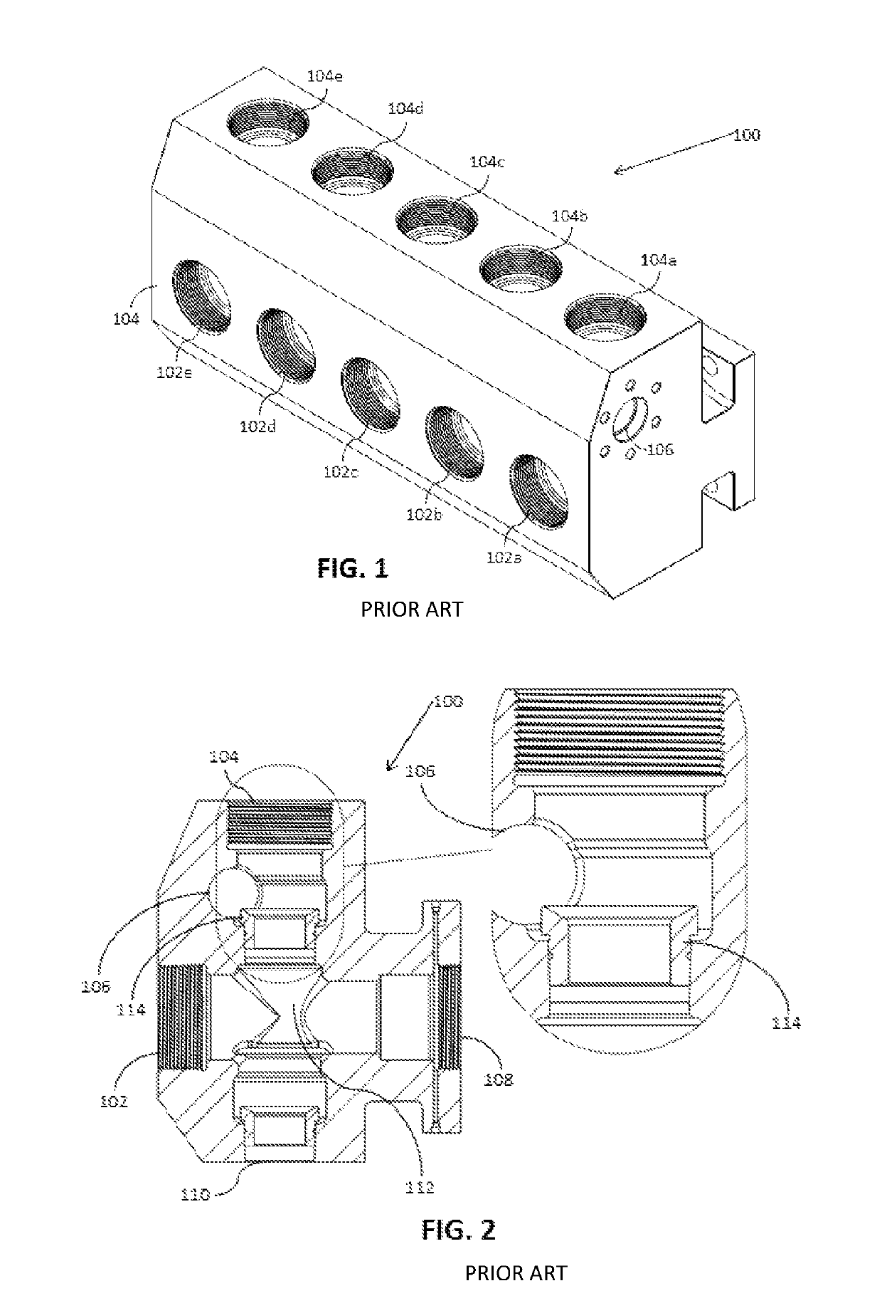
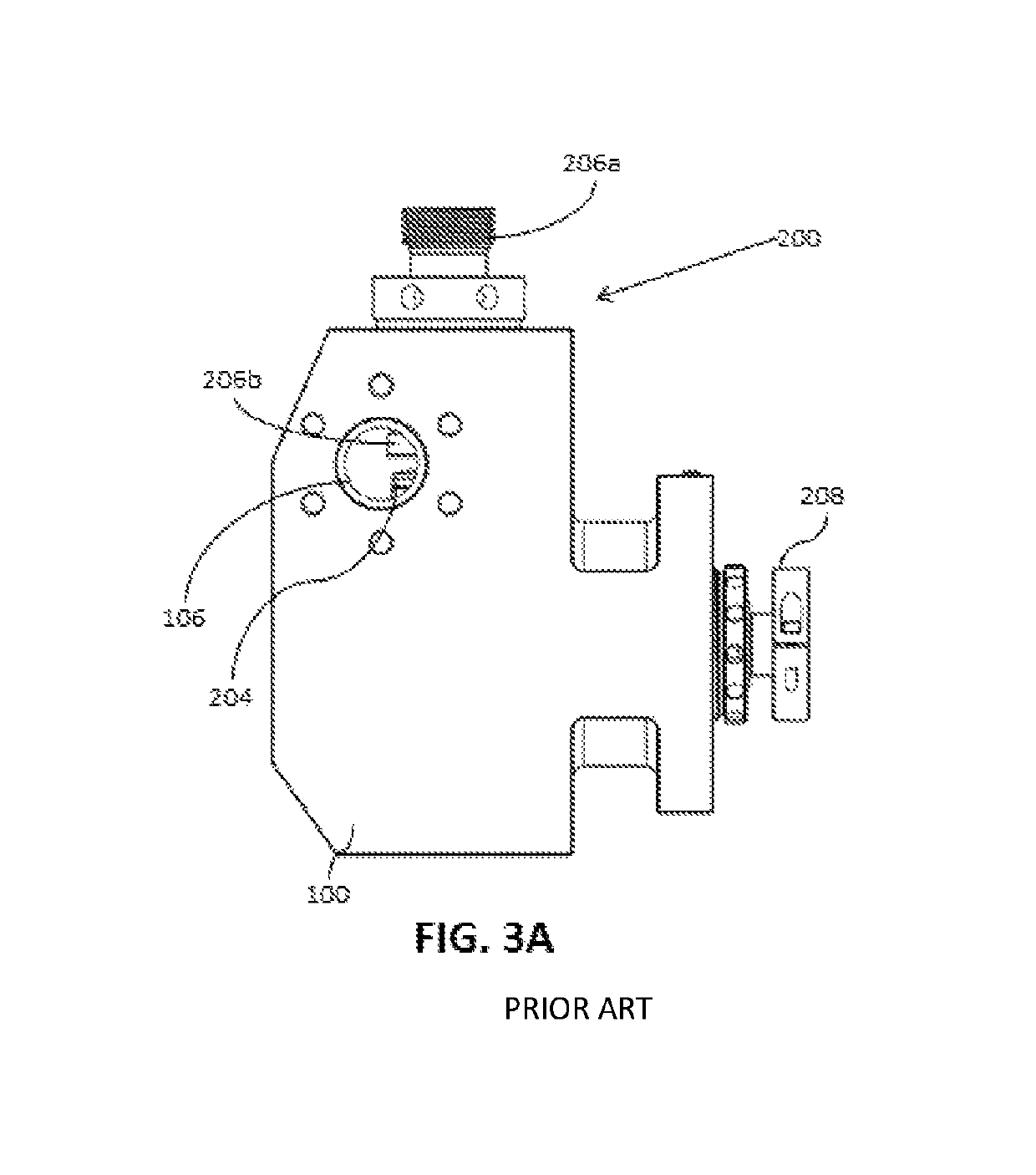
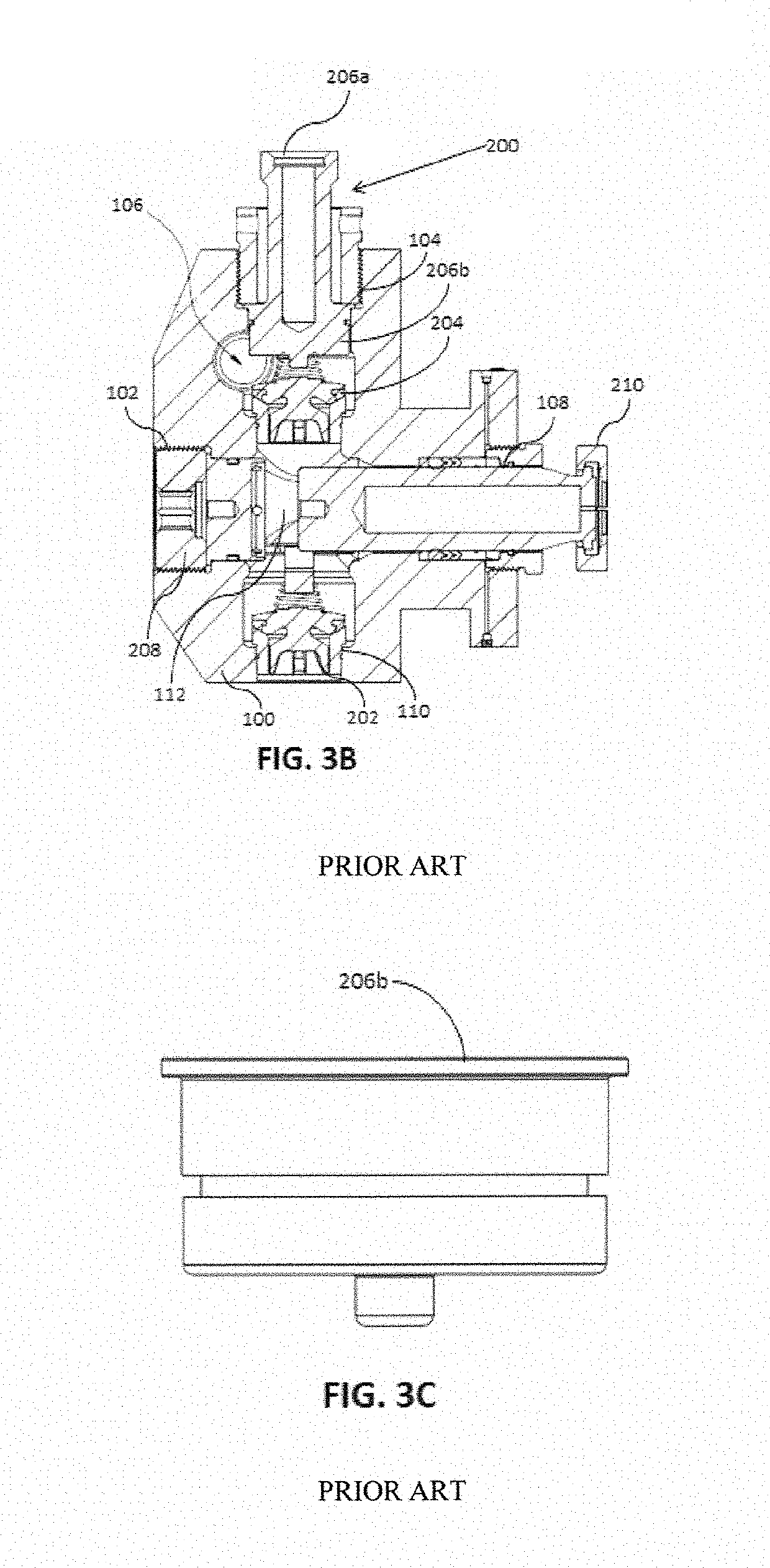
High pressure flow of fluid in the fluid end 100 of conventional blocks often leads to cavitation therein and lessens the life and performance of the fluid end 100.
Flow of high pressure fluid in the fluid end 100 may also lead to widening of cracks and crevices formed therein, and may further lead to fracturing of the fluid end 100.
If the pressure inside the fluid end 100 is very high, the fluid may be spewed out at a high velocity causing

Method used


Image

  • Discharge cap and block for a fluid end assembly
  • Discharge cap and block for a fluid end assembly
  • Discharge cap and block for a fluid end assembly

Examples


Example

EXAMPLE

[0050]A conventional design and the improved fluid end assembly design were operated under the same conditions and compared for run times and cavitation activity.

[0051]8 redesigned fluid end assemblies were tested using Hercules brand pumps. The redesigned bore was 4.5″, the discharge cap was conical in shape and the decks were recessed. The fluid end assemblies and pumps operated for at least a 2 hour fracturing stage (also called a pumping time) at approximately 8000 psi. at the wellhole. 400,000 lbs of 100 Mesh fracturing sand was used; It was found that the Hercules improved fluid end assemblies had a life of about 750 hours average (average over the 8 pump assemblies); the Conventional fluid end assemblies had a life of about 300 hours average (average over the 8 pump assemblies). The inventive assembly operated longer without cavitation or pump failure compared to the conventional design.

[0052]During the experiments, the inventor was looking for reducing the differentia...


PUM


Abstract

Disclosed herein is an improved fluid end discharge cap and bore to minimize or avoid cavitation during use of a reciprocating fluid end pump and hence prolong the use and life of the fluid end assembly. The improved design included modifying the current cylindrical discharge cover or cap to a tapered, conical or convex design, enlarging the discharge bore, and recessing seat decks into the suction and discharge bores, to avoid fluid flow obstructions and increase volume flow. The pump outlet bore was enlarged and the bore height and diameter were increased to further increase flow. The conventional design has edges and ninety-degree angles which tended to allow for fluid media to remain in the bore and trigger pump cavitation. The current inventive design has eliminated restrictions, in particular 90° angles, to allow uninterrupted fluid flow therein.

Description

FIELD OF THE INVENTION[0001]The present invention relates to a reciprocating pump. More particularly, the present invention relates to an improved block and discharge cap for a fluid end assembly of a reciprocating pump.DESCRIPTION OF THE RELATED ART[0002]The present application is filed under request for prioritized examination track one (1) under 37 CFR 1.102(e).[0003]A reciprocating pump is a positive-displacement pump that typically utilizes a crankshaft mechanism for pumping fluid at high pressures. Examples of the reciprocating pump include piston pumps, plunger pumps, and diaphragm pumps. The reciprocating pump is used to pump fluid into a storage container for storing the fluid. A plunger pump includes a plunger that reciprocates in a chamber and creates volume changes that result in flow of fluid in to and out of the chamber. When the plunger retracts, the fluid flows into the chamber. When the plunger extends, the fluid is forced out of the chamber. The reciprocating pump ...

Claims


Application Information

Patent Timeline
IPC IPC(8): F04B53/16F04B53/10F04B19/22F04B1/04F04B53/14
CPCF04B53/10F04B53/162F04B1/0421F04B53/16F04B19/22F04B53/1087F04B53/14F04B1/0461F04B1/0538F04B11/0091
Inventor GUERRA, JESSE
Owner VP SALES & COMPANY
Why Eureka
Try Eureka