Supercharge Your Innovation With Domain-Expert AI Agents!

Combustion staging system

a technology of combustion staging and combustion chamber, which is applied in the direction of efficient propulsion technologies, machines/engines, lighting and heating apparatus, etc., can solve the problems of not meeting the pressure requirement, increase and improve the control of the fuel pressure in the mains manifold. , the effect of increasing the pressure variation of the mains manifold

Active Publication Date: 2019-11-05
ROLLS ROYCE PLC
View PDF21 Cites 2 Cited by
  • Summary
  • Abstract
  • Description
  • Claims
  • Application Information

AI Technical Summary

Benefits of technology

The patent describes a system for controlling fuel pressure in a gas turbine engine. The system includes fuel injectors with mains check valves that open when fuel pressure in the mains manifold exceeds a predetermined level relative to gas pressure in the combustor. The controller selects a target pressure for pilot-only operation to prevent leakage through the check valves. The system also includes a splitting unit that partially selects the mains manifold to reduce the supply to the combustor, but this may increase pressure variation in the mains manifold. The system also includes a fuel recirculating control valve and a recirculating flow return valve to control the cooling flow and pressure raising orifice, respectively. The system can also include a pilot manifold segment restrictable by a lean blow out protection valve to decrease the pilot fuel flow to the injectors. The technical effects of the system include improved control of fuel pressure in the mains manifold and reduction of leakage flow through the fuel injectors.

Problems solved by technology

In pilot-only mode in particular, it can be problematic to meet this pressure requirement across the operating envelope of the system due to variation in the tolerances of the CFO 146 and the PRO 147.

Method used


Image

  • Combustion staging system
  • Combustion staging system
  • Combustion staging system

Examples


Embodiment Construction

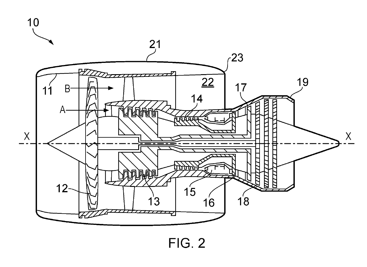
[0046]With reference to FIG. 2, a ducted fan gas turbine engine incorporating the invention is generally indicated at 10 and has a principal and rotational axis X-X. The engine comprises, in axial flow series, an air intake 11, a propulsive fan 12, an intermediate pressure compressor 13, a high-pressure compressor 14, combustion equipment 15, a high-pressure turbine 16, an intermediate pressure turbine 17, a low-pressure turbine 18 and a core engine exhaust nozzle 19. A nacelle 21 generally surrounds the engine 10 and defines the intake 11, a bypass duct 22 and a bypass exhaust nozzle 23.

[0047]During operation, air entering the intake 11 is accelerated by the fan 12 to produce two air flows: a first air flow A into the intermediate-pressure compressor 13 and a second air flow B which passes through the bypass duct 22 to provide propulsive thrust. The intermediate-pressure compressor 13 compresses the air flow A directed into it before delivering that air to the high-pressure compres...


PUM


Abstract

A combustion staging system includes a splitting unit which receives a metered fuel flow and controllably splits the received fuel flow into pilot and mains flows. Pilot and mains fuel manifolds distribute fuel from the splitting unit to the pilot and mains stages. The splitting unit selects and deselects pilot-only operation. Both pilot and mains manifolds are selectable for pilot and mains operation. A cooling flow recirculation line has a delivery section arranged to provide a cooling flow of fuel to the mains manifold when it is deselected during pilot-only operation. Cooling flow enters the delivery section from a high pressure fuel zone of the engine and exits the return section to a low pressure fuel zone of the engine. A controller adjusts the splitting unit during pilot-only operation to partially select the mains manifold thereby increasing the pressure in the mains manifold to meet a target fuel pressure therein.

Description

FIELD OF THE INVENTION[0001]The present invention relates to a combustion staging system for fuel injectors of a multi-stage combustor of a gas turbine engine.BACKGROUND[0002]Multi-stage combustors are used particularly in lean burn fuel systems of gas turbine engines to reduce unwanted emissions while maintaining thermal efficiency and flame stability. For example, duplex fuel injectors have pilot and mains fuel manifolds feeding pilot and mains discharge orifices of the injectors. At low power conditions only the pilot stage is activated, while at higher power conditions both pilot and mains stages are activated. The fuel for the manifolds typically derives from a pumped and metered supply. A splitter valve can then be provided to selectively split the metered supply between the manifolds as required for a given staging.[0003]A typical annular combustor has a circumferential arrangement of fuel injectors, each associated with respective pilot and mains feeds extending from the cir...

Claims


Application Information

Patent Timeline
Patent Type & Authority Patents(United States)
IPC IPC(8): F23R3/28F23K5/06F23R3/34F02C9/36F02C9/26F02C7/232F02C7/228F02C9/34
CPCF02C9/34F02C9/36F23K5/06F23R3/343F23R3/283F02C9/263F02C7/228F23R3/346F02C7/232F23R3/34Y02T50/671F23R2900/00004Y02T50/60
Inventor STEVENSON, ANDREWTHOMPSON, GRAHAM
Owner ROLLS ROYCE PLC
Features
  • R&D
  • Intellectual Property
  • Life Sciences
  • Materials
  • Tech Scout
  • Unparalleled Data Quality
  • Higher Quality Content
  • 60% Fewer Hallucinations
Learn More