Sealing arrangement using flexible seals

a sealing arrangement and flexible technology, applied in the direction of engine sealing, leakage prevention, machines/engines, etc., can solve the problems of loss of performance or resistance, worst recoverable leakage of each brush seal, failure of flexible elements, etc., to reduce the performance of flexible seals, reduce the effect of pressure drop, and reduce the radial clearan

Inactive Publication Date: 2005-05-19
ALSTOM TECH LTD
View PDF9 Cites 25 Cited by
  • Summary
  • Abstract
  • Description
  • Claims
  • Application Information

AI Technical Summary

Benefits of technology

[0018] In particular, in the above example, if the performance of each individual flexible seal (e.g. brush seal) is degraded (e.g. by shortening the bristles in some circumferential sections of the seal, or by drilling by-pass holes through the seal, allowing leakage around the back of the seal, or by installing the seals with increased radial clearance, or by careful control of the leakage around the back of the spring-backed gland, or if the seal is split into segments leaving gaps between them), limiting the pressure drop caused by the seal, so that the performance of the flexible seal is reduced to being equivalent to a labyrinth (fin seal) restriction with a clearance of 0.15 mm, then under the same scenario as above (bristles of two brush seals stuck behind the backing ring), the maximum pressure drop (Δpmax) that the third brush seal would see is now reduced to 25 bar. Thus, in this case, this seal would not be over-loaded and performance of the system would be unchanged when the bristles of the remaining brush seals returned to their normal operating positions.
[0019] There will be a penalty in increased leakage flow through the sealing arrangement if the brush seals are protected in this way. Replacing three of 21 labyrinth restrictions with a clearance of 1.0 mm by three brush seals with an equivalent labyrinth clearance of 0.1 mm reduces leakage flow to 44% ((21*1) / (18*1+3*10)) of the leakage through the sealing arrangement with 21 labyrinth restrictions. If the performance of each brush seal is degraded to a labyrinth clearance equivalents of 0.15 mm, the leakage increases to 55% of the pure labyrinth system.

Problems solved by technology

However, in steam turbine applications, sealing arrangements will often have to be designed for pressure drops significantly greater than 25 bar, sometimes more than 50 bar.
With flexible (e.g. brush or leaf) seals, non-linear movement of the flexible elements, due to friction between the flexible elements and their supporting structure, can result in situations where one of the seals in a multiple seal configuration is exposed to a significantly larger proportion of the total pressure drop than the design intent and lead to failure of the flexible element.
Once a flexible seal has failed, further failures will occur in a cascade fashion due to the increased loading on the remaining seals.
The worst recoverable leakage (loss of performance or decrease in resistance) of each brush seal will occur if, following some large radial vibration of the rotor, say, the brush seal bristles become temporarily stuck up behind the backing ring, owing to friction.
So, this seal would suffer permanent damage from over-loading.
Once damage has occurred to one seal, the loading on the other brush seals will be increased when their bristles become free again and consequently the likelihood of further bristle pack over-loading is increased.
Once damage has started to occur, any such system has the potential to cascade rapidly towards total failure in this manner.

Method used


Image

  • Sealing arrangement using flexible seals
  • Sealing arrangement using flexible seals
  • Sealing arrangement using flexible seals

Examples


Embodiment Construction

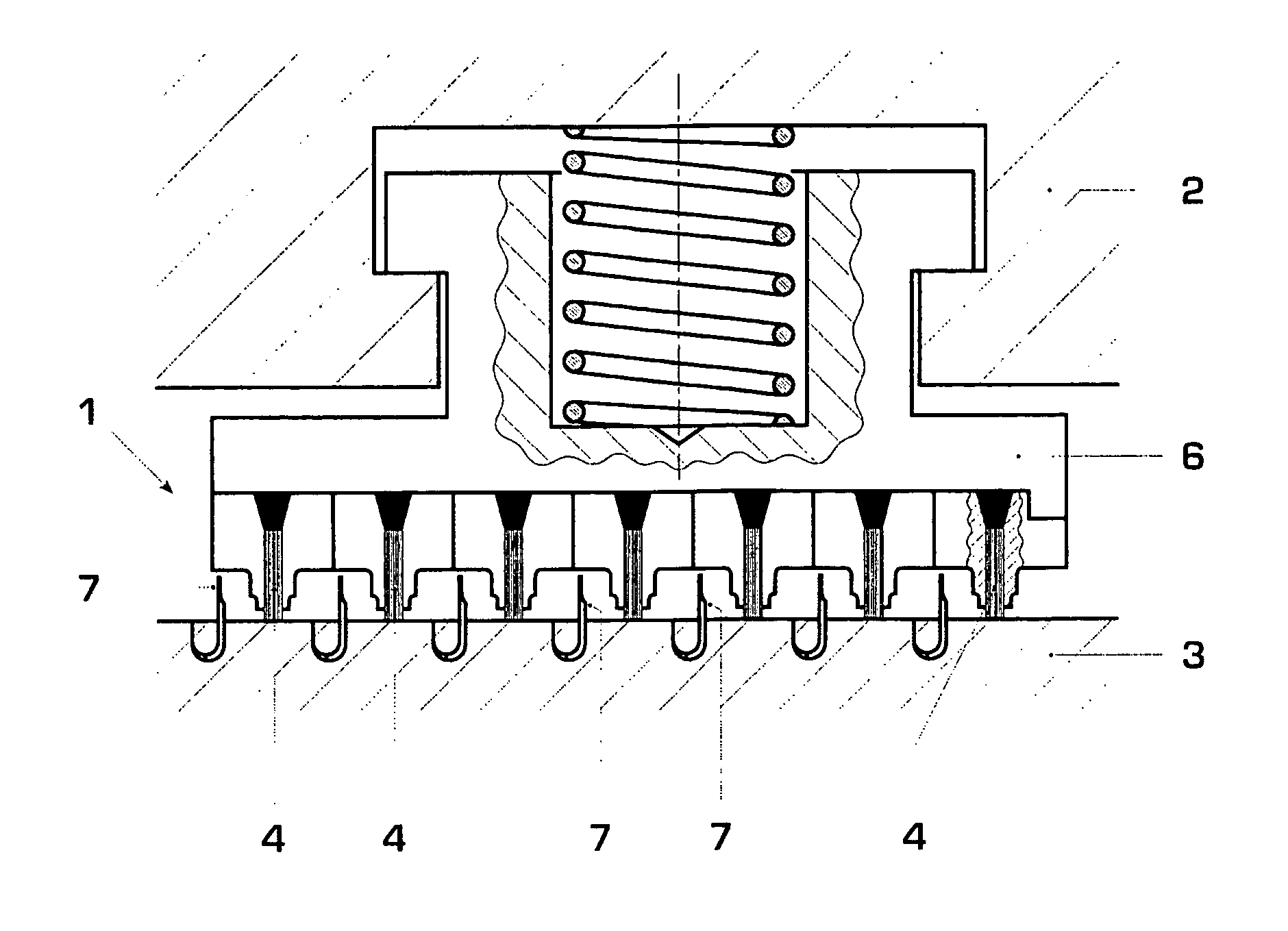
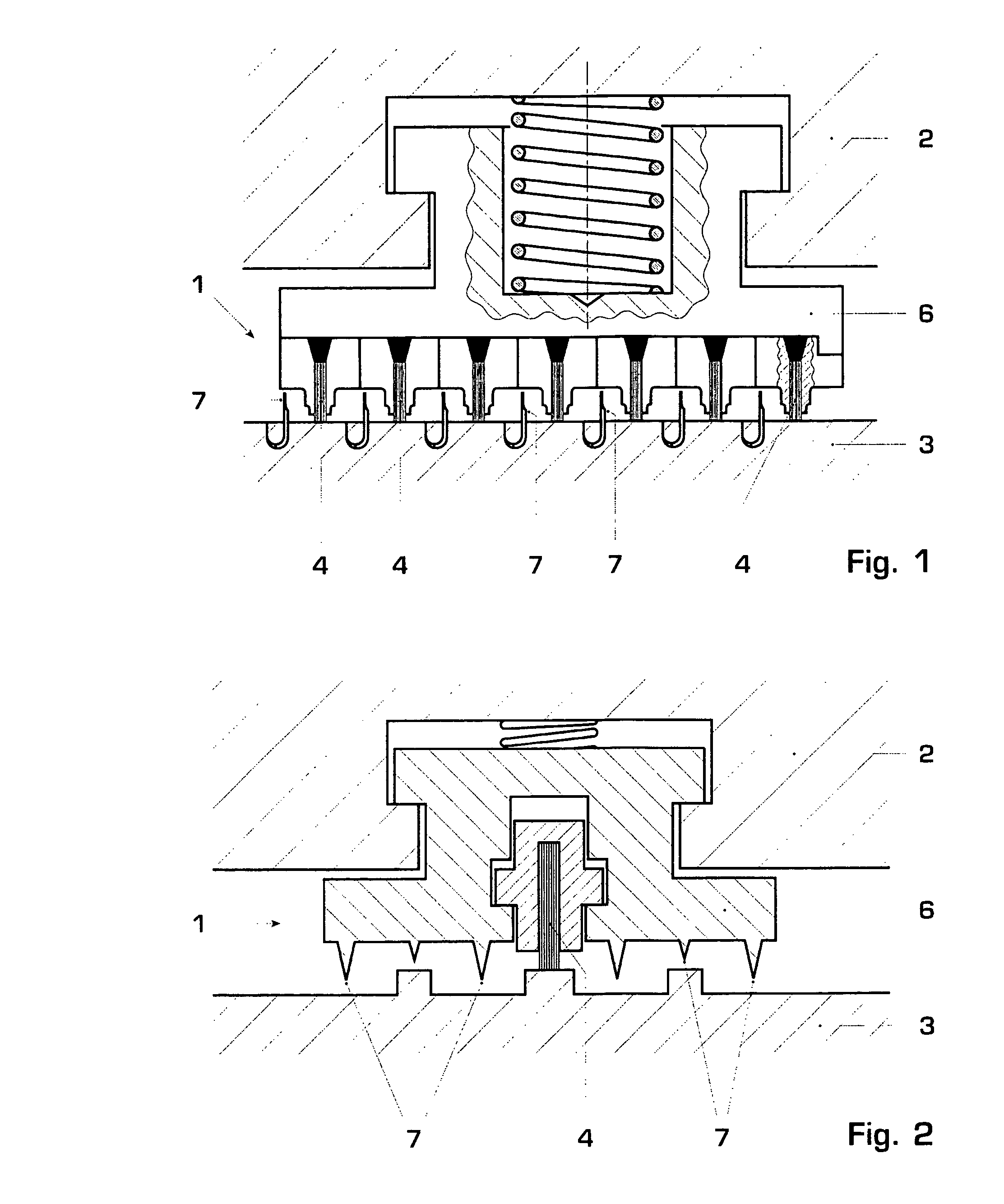
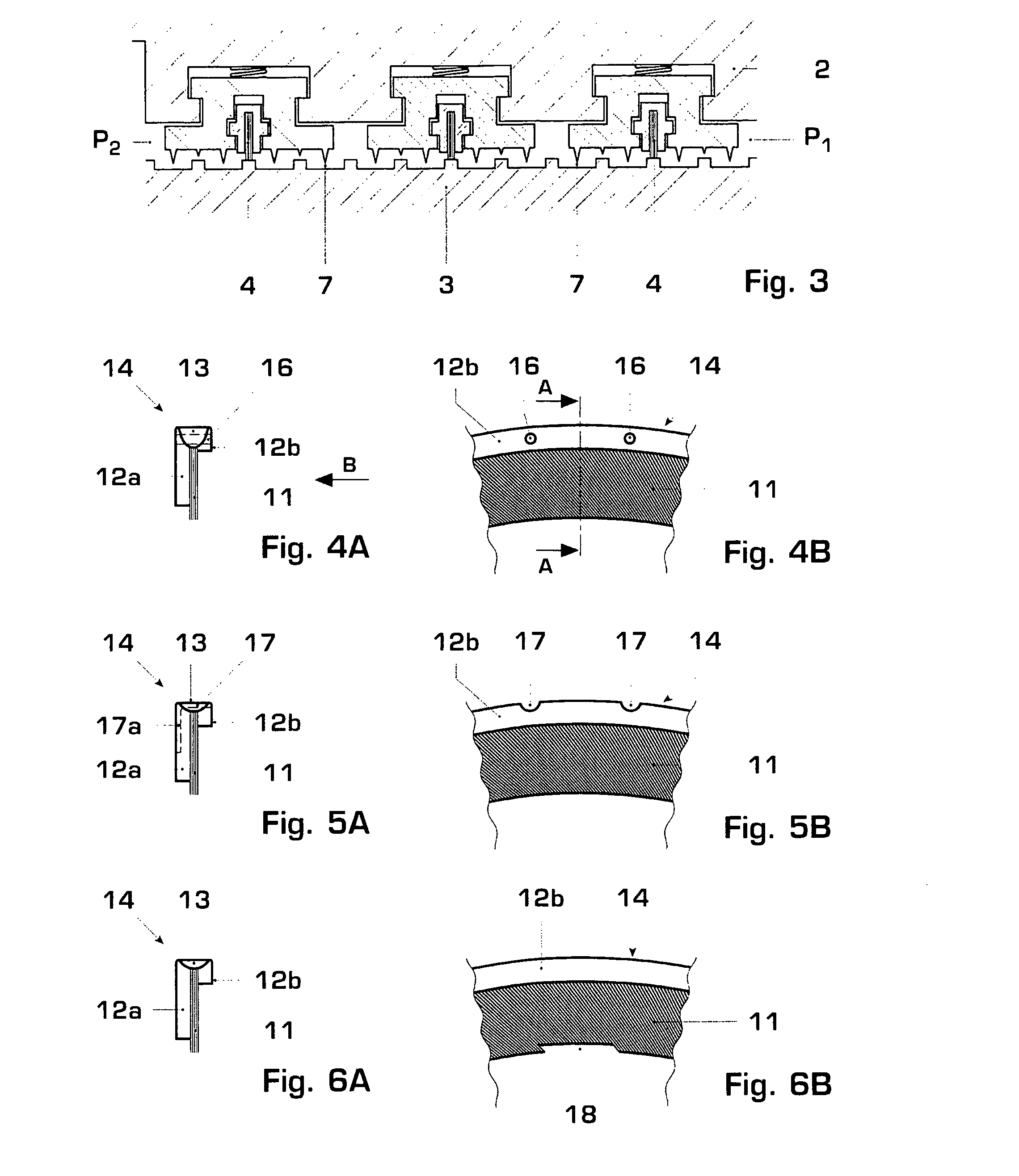
[0031] The brush seal 14 shown in FIGS. 4A and 4B is a form of flexible seal comprising an annular brush 11 (serving as a ring of flexible sealing material) consisting of a closely packed array of bristles, the outer ends of which are trapped between two metallic backing members 12a, 12b which are connected by a weld 13 which also secures the bristles 11. The downstream backing member 12a is longer than the upstream backing member 12b, so as to support the brush 11 against the pressure on the upstream side of the brush seal. This construction is one of several brush seal constructions already known.

[0032] The brush seal 14 is one of a series of seals in a sealing arrangement between first and second relatively rotatable bodies of a turbine. In a steam turbine, for example, the sealing arrangement may be between a stationary casing and a balance piston, which is part of the rotor. Alternatively or additionally, the sealing arrangement may be provided between a stationary casing and ...


PUM


Abstract

A sealing arrangement is provided between relatively rotatable bodies of a machine in which, in operation, a relatively high pressure (P1) exists on one side of the sealing arrangement and a relatively low pressure (P2) exists on the other side, the pressure difference (P1-P2) being up to a predetermined maximum pressure difference (ΔPmax). The sealing arrangement includes a series of seals, the pressure dropping across each successive seal from the high pressure side of the sealing arrangement to the low pressure side. At least two of the seals are flexible seals, e.g. brush or leaf seals. Each flexible seal 14 is designed to function under a pressure drop (Δp) up to a predetermined maximum pressure drop (Δpmax) across the flexible seal 14 and to provide a given resistance to fluid flow. Each flexible seal 14 is capable of recovering from an abnormal condition, due to normal operation of the machine, in which the resistance of the flexible seal to fluid flow decreases from a normal level to a substantially lower level. The series of seals are arranged in such a manner that the pressure drop across each flexible seal is less than the predetermined maximum pressure drop (Δpmax) when the pressure difference (P1-P2) between the high pressure side of the sealing arrangement and the low pressure side is equal to the said predetermined maximum pressure difference (ΔPmax) and another one of the flexible seals has suffered a recoverable decrease in its resistance to fluid flow. In one embodiment the flexible seal 14 is provided with a permanent by-pass path 16 communicating between its upstream and downstream sides.

Description

[0001] This application claims priority to British application number 0324076.9, filed 14 Oct. 2003, the entirety of which is incorporated by reference herein. BACKGROUND OF THE INVENTION [0002] 1. Field of the Invention [0003] This invention relates to sealing arrangements in general, in particular a sealing arrangement between first and second relatively rotatable bodies of a machine, more particularly a turbo machine. [0004] 2. Brief Description of the Related Art [0005] The development of flexible seal, e.g. brush seal, or leaf or foil seal, technology over the last two decades has principally been in the field of gas turbines. In such applications, the pressure drop across the seal assembly will not usually be more than 25 bar. [0006] However, in steam turbine applications, sealing arrangements will often have to be designed for pressure drops significantly greater than 25 bar, sometimes more than 50 bar. By way of example, in a high pressure cylinder the steam inlet pressure m...

Claims


Application Information

Patent Timeline
Patent Type & Authority Applications(United States)
IPC IPC(8): F01D11/00F01D11/02
CPCF01D11/025F01D11/001
Inventor HOGG, SIMONWALKER, PETER JOHN
Owner ALSTOM TECH LTD
Why Eureka
Try Eureka