Airfoil body including a moveable section of an outer surface carrying an array of transducer elements

a technology of transducer elements and airframes, which is applied in the direction of energy-efficient board measures, transportation and packaging, and efficient propulsion technologies. it can solve the problems of photovoltaic cells, adversely affecting the integrity of solar panels, and large surface area of photovoltaic cells needed to provide sufficient electrical power for propelling an aircra

Active Publication Date: 2019-11-05
SOLAERO TECH CORP
View PDF22 Cites 13 Cited by
  • Summary
  • Abstract
  • Description
  • Claims
  • Application Information

AI Technical Summary

Benefits of technology

[0020]According to this aspect, the transducers may be selectively exposed or stowed on one of the spindles. In some examples, the flexible support may extend between the first spindle and the second spindle and over a portion of the suction surface. The transducers, e.g. solar cells can thus be positioned on an outer surface of a wing. In other examples, the flexible support member may extend between the first and the second spindle inside the airfoil body. The skin of the airfoil body may be made translucent or transparent. Solar cells may be arranged on the flexible support member inside the airfoil body and provide power. In the case of higher (predicted) loads, or in the case of (predicted) deflection or deformation of the wing above a predetermined threshold, the solar cells may be stowed on one of the spindles. It can thus be avoided that the solar cells become damaged.

Problems solved by technology

The surface area of photovoltaic cells needed to provide sufficient electrical power for propelling an aircraft may be significant.
However, long, lightweight wings may be highly flexible, presenting a number of problems for the photovoltaic cells due to the loads imposed on the wings during flight.
As noted in US Patent Application Publication 20160167764, the flexing of the wings during flight may cause the solar panels to experience high strains that can adversely affect the integrity of the solar panels.
These strains may also result in buckling or wrinkling of the solar panels which may trip the airflow boundary layer over the wings from laminar to turbulent, or cause air flow separation, which may significantly reduce the aerodynamic performance of the aircraft.
The integrity of the solar panels and / or the aerodynamic performance of the wings may also be adversely affected by large temperature swings experienced by the aircraft during flight.
These temperature swings may result in excessive stresses and strains between the solar panel and the wing structure, due to differences in thermal expansion.

Method used


Image

  • Airfoil body including a moveable section of an outer surface carrying an array of transducer elements
  • Airfoil body including a moveable section of an outer surface carrying an array of transducer elements
  • Airfoil body including a moveable section of an outer surface carrying an array of transducer elements

Examples


Embodiment Construction

[0053]Details of the present invention will now be described including exemplary aspects and embodiments thereof. Referring to the drawings and the following description, like reference numbers are used to identify like or functionally similar elements, and are intended to illustrate major features of exemplary embodiments in a highly simplified diagrammatic manner. Moreover, the drawings are not intended to depict every feature of the actual embodiment nor the relative dimensions of the depicted elements, and are not drawn to scale.

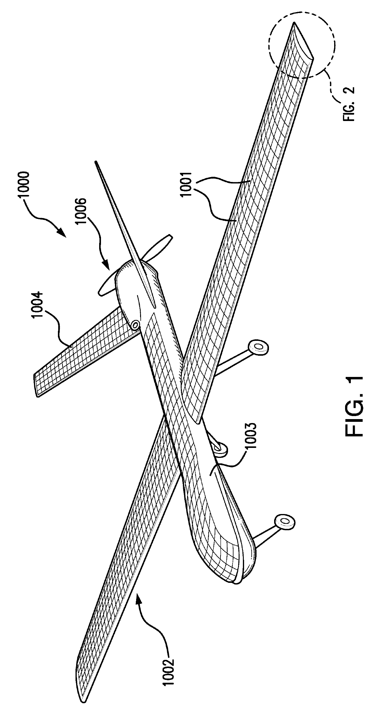
[0054]FIG. 1 is a perspective view of an aircraft 1000 having a solar cell assembly 1001 positioned on a suction surface of the wings 1002 of the aircraft 1000. The aircraft 1000 in this example is an unmanned aerial vehicle (UAV). Such a UAV may be used e.g. in surveillance missions.

[0055]In the example of FIG. 1, solar cells are not only provided on the wings 1002, but also on a top surface of a fuselage 1003, and on the suction surfaces of the horizon...


PUM


Abstract

An airfoil body for an aircraft extending from an inner end to an outer end, between a leading edge and a trailing edge and having a pressure surface and a suction surface, the airfoil body having an outer surface and an inner support structure, the outer surface including a fixed skin section and a movable skin section, wherein the movable skin section comprises a first portion including an array of transducer elements, and the airfoil body including an actuator for moving the movable skin section to selectively position the transducer elements on the outer surface.

Description

TECHNICAL FIELD[0001]The present invention relates generally to an airfoil body for an aircraft. More particularly, the present invention relates to airfoil bodies comprising transducer elements, and in particular an array of solar cells. Furthermore, the present invention relates to a wing section or wing for a manned or unmanned aerial vehicle (UAV).BACKGROUND[0002]Aircraft that have arrays of photovoltaic solar cells on the aircraft's wings for converting solar energy into electrical power are known. The electrical power generated by such solar cells may be used to operate on-board aircraft systems and / or to propel the aircraft, typically using one or more electric motors and propellers. The solar arrays are typically mounted on a suction surface (upper surface) of the wings since such location provides favorable exposure to sunlight.[0003]Designing solar powered aircraft, particularly those flying at high altitudes, has several challenges. The surface area of photovoltaic cells ...

Claims


Application Information

Patent Timeline
Patent Type & Authority Patents(United States)
IPC IPC(8): H01L31/0445B64C3/26B64D27/24B64C39/02H02S30/20B64C3/48H02S20/00
CPCH01L31/0445B64D27/24B64C3/48H02S30/20B64C3/26B64C39/024B64C2201/066B64C2201/042B64C2201/021B64D2211/00H02S20/00B64C2201/104H01L31/048Y02E10/50Y02T50/50Y02T50/60H02S20/30B64U50/34B64U30/10B64U10/25B64U50/19
Inventor YANG, LEI
Owner SOLAERO TECH CORP
Why Eureka
Try Eureka