Method for diagnosing a fault in current-mode control of an electric motor in a motor vehicle

a current-mode control and motor vehicle technology, applied in the field of motor vehicles, can solve the problems of not being able to detect a fault in the microcontroller, being inaccurate or even random in the method, and presenting a major drawback, so as to achieve simple, reliable and effective results

Active Publication Date: 2019-11-05
CONTINENTAL AUTOMOTIVE FRANCE +1
View PDF8 Cites 1 Cited by
  • Summary
  • Abstract
  • Description
  • Claims
  • Application Information

AI Technical Summary

Benefits of technology

[0012]An aspect of the invention aims to solve these drawbacks at least partly by providing a simple, reliable and effective solution for measuring the dead times inserted into the control signals for controlling an electric motor.
[0023]The method according to an aspect of the invention makes it possible to calculate, in real time, the actual dead time in order to take into account the negative effects of the transistors and filters on the inserted dead time. The actual dead time is accurately calculated on the basis of the measured and formatted control signals. The method thus makes it possible to measure with accuracy, of the order of 250 ns, the actual dead time present in the control signals in order to effectively detect a fault in said control signals.
[0035]The use of a theoretical straight line makes it possible to refine the calculation of the dead time such that it can be calculated with an accuracy of the order of 250 ns or less.

Problems solved by technology

However, such a solution does not make it possible to detect a fault in the microcontroller 10.
Moreover, the latency time taken for such calculations allows an accuracy only of the order of a microsecond to be obtained, i.e. twice the maximum duration of a dead time (500 ns), particularly as the dead time is affected by the effects of the current flowing through the transistors, the measurement errors caused by the measurement module 40, the delays introduced by the electronic filters, and the rise and fall times of the primary signals SEH1, SEB1 and of the control signals U, V, W, thereby making the method inaccurate or even random and therefore presenting a major drawback.

Method used


Image

  • Method for diagnosing a fault in current-mode control of an electric motor in a motor vehicle
  • Method for diagnosing a fault in current-mode control of an electric motor in a motor vehicle
  • Method for diagnosing a fault in current-mode control of an electric motor in a motor vehicle

Examples


Embodiment Construction

[0069]The device according to an aspect of the invention is intended to be mounted in a motor vehicle with an electric motor for the purpose of current-mode controlling said motor and diagnosing a fault in the control of said motor.

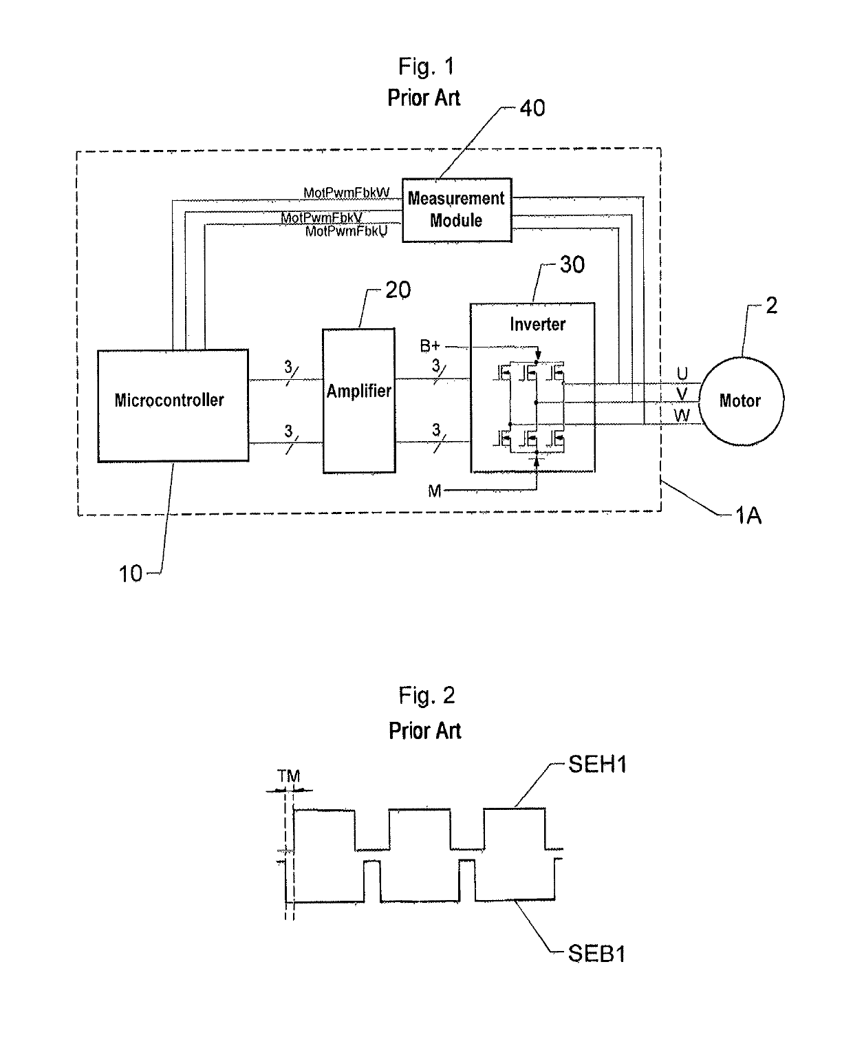
[0070]With reference to FIG. 8, the electric motor 2 is a motor with three phases U, V, W, or a three-phase motor, but it goes without saying that an aspect of the invention could be applied to any electric motor for a motor vehicle.

[0071]Each phase U, V, W of the motor 2 is current-mode controlled by a respective control signal U, V, W generated by the control device 1B.

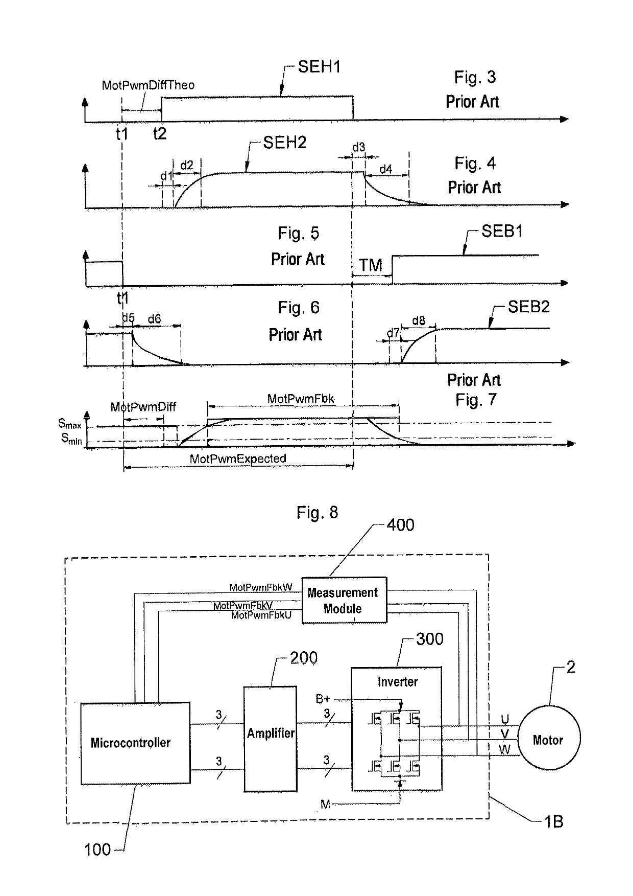
[0072]To this end, the control device 1B comprises a microcontroller 100, an amplifier 200 and a power stage taking the form of an inverter 300.

[0073]The microcontroller 100 is configured to generate three pairs of pulse-width modulated (PWM) voltage signals, referred to as initial signals, a single pair of which has been shown in FIGS. 3 and 5 for the sake of clarity. The high-stage sign...


PUM


Abstract

A method for diagnosing a fault in the control of a three-phase electric motor current-mode controlled by a control signal. The method makes it possible to calculate the actual dead time present in each of the three control signals at a given time on the basis of compensated temporal offsets for each phase of the motor, of a predetermined measurement error common to the three phases of the motor and of a value of a amplitude of the current flowing through the transistors of the three pairs of transistors at the given time so as to detect a fault in the control of the motor when the absolute value of the calculated difference is higher than a predetermined detection threshold.

Description

CROSS REFERENCE TO RELATED APPLICATIONS[0001]This application is the U.S. National Phase Application of PCT International Application No. PCT / FR2017 / 050856, filed Apr. 10, 2017, which claims priority to French Patent Application No. 1653344, filed Apr. 15, 2016, the contents of such applications being incorporated by reference herein.FIELD OF THE INVENTION[0002]The invention relates to the field of motor vehicles and relates more particularly to a method for diagnosing the current-mode control of an electric motor of a motor vehicle. The invention applies in particular to the current-mode control of a three-phase electric motor.BACKGROUND OF THE INVENTION[0003]In a motor vehicle with a three-phase electric motor, the motor is controlled in a known manner by using three AC current-mode control signals delivered by a control device.[0004]In one existing solution illustrated in FIG. 1, this device 1A comprises a microcontroller 10, an amplifier 20 and a power stage taking the form of a...

Claims


Application Information

Patent Timeline
Patent Type & Authority Patents(United States)
IPC IPC(8): H02M1/38H02P27/08H02M1/32H02M7/219H02P29/024H02M7/5387
CPCH02P27/08H02P29/0241H02M1/32H02M1/38H02M7/219H02M7/53871
Inventor PARETTE, MICHEL
Owner CONTINENTAL AUTOMOTIVE FRANCE
Why Eureka
Try Eureka