

Method for coupling two sub-shafts
a technology of subshafts and couplings, applied in the direction of couplings, machines/engines, engine starters, etc., can solve the problems of disadvantageous vibration of shaft trains, insufficient waste heat available to drive steam turbines, and the achievement of desired coupling angle only by acciden
- Summary
- Abstract
- Description
- Claims
- Application Information
AI Technical Summary
Benefits of technology
Problems solved by technology
Method used
Image

Examples
Embodiment Construction
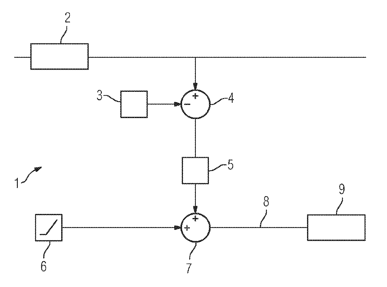
[0017]Firstly, the second sub-shaft is rotated with an initial rotational speed which is lower than the rotational speed of the first sub-shaft. The initial rotational speed can be about 0.5 Hz to 1.5 Hz, in particular 0.9 Hz to 1.1 Hz, lower than a reference mains frequency. This ensures that, even in the event of typically occurring fluctuations of the rotational speed of the first sub-shaft, the second sub-shaft is slower than the first sub-shaft at the initial rotational speed. The reference mains frequency 3 is, for example, 50 Hz or 60 Hz. The initial rotational speed can be entered as a set point into a rotational speed control system 9 of the second sub-shaft.
[0018]As can be seen from the FIGURE, the mains frequency 2 of the mains supply is measured. This can be done electrically or by measuring the rotational speed of the first sub-shaft. A difference 4 is then formed between the mains frequency 2 and the reference mains frequency 3 of the mains supply. The difference 4 is ...
PUM
 Abstract
Description
Claims
Application Information