Air conditioning system

a technology of air conditioning system and air flow, which is applied in the field of air conditioning system, can solve the problems of reducing room comfort and increasing cooling load, and achieve the effects of reducing the increase in the temperature of the blowing air, reducing the comfort of the room, and increasing the cooling load

Active Publication Date: 2019-12-03
MITSUBISHI ELECTRIC CORP
View PDF16 Cites 0 Cited by
  • Summary
  • Abstract
  • Description
  • Claims
  • Application Information

AI Technical Summary

Benefits of technology

[0007]The present invention has been made to solve the above problems, and is intended to provide an air conditioning system capable of regulating the temperature of blown out air within a desired range, while reducing increase in power consumption and preventing the configuration and control from being complicated.
[0009]The air conditioning system of the present invention cools air in the heat exchanger and then supplies the air in the room. This makes it possible to reduce an increase in temperature of the blown out air during the humidifying operation in winter, for example, and reduce both reduction in comfort in the room and increase in a cooling load. Moreover, since the air conditioning system includes a single refrigerant circuit, it can have a simple configuration and requires no complicated control.

Problems solved by technology

In such an air conditioning system, the humidification raises the temperature of the blown out air, leading to reduction in comfort in the room and increase in a cooling load.

Method used


Image

  • Air conditioning system
  • Air conditioning system
  • Air conditioning system

Examples


first embodiment

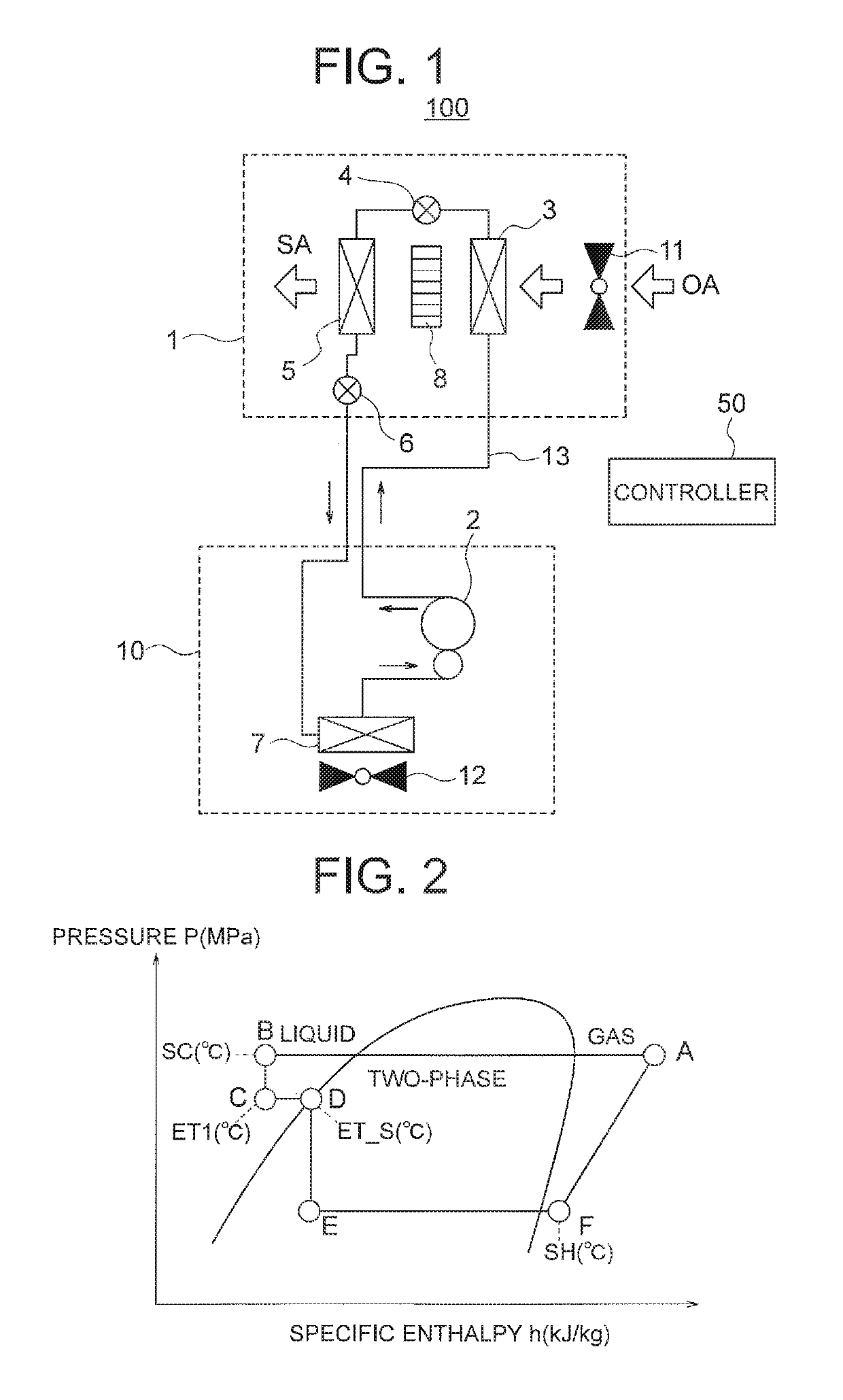
[0023]FIG. 1 is a diagram illustrating a configuration of an air conditioning system 100 according to a first embodiment of the present invention. The air conditioning system 100 takes in air outside a room and humidifies it, and supplies the humidified air into the room. The air conditioning system 100 includes an outside air processing unit 1, an outdoor unit 10, and a controller 50. The outside air processing unit 1 and outdoor unit 10 are connected to each other through refrigerant piping 13.

[0024]The outside air processing unit 1 includes a first heat exchanger 3 as a condenser, a first decompressor 4, a second heat exchanger 5 as a heat exchanger, and a second decompressor 6. The first heat exchanger 3 and second heat exchanger 5 are disposed to face each other. A humidifier 8 is disposed between the first heat exchanger 3 and the second heat exchanger 5.

[0025]An indoor blower fan 11 as a blower fan that takes in air from outside the room is disposed on a side of the first hea...

second embodiment

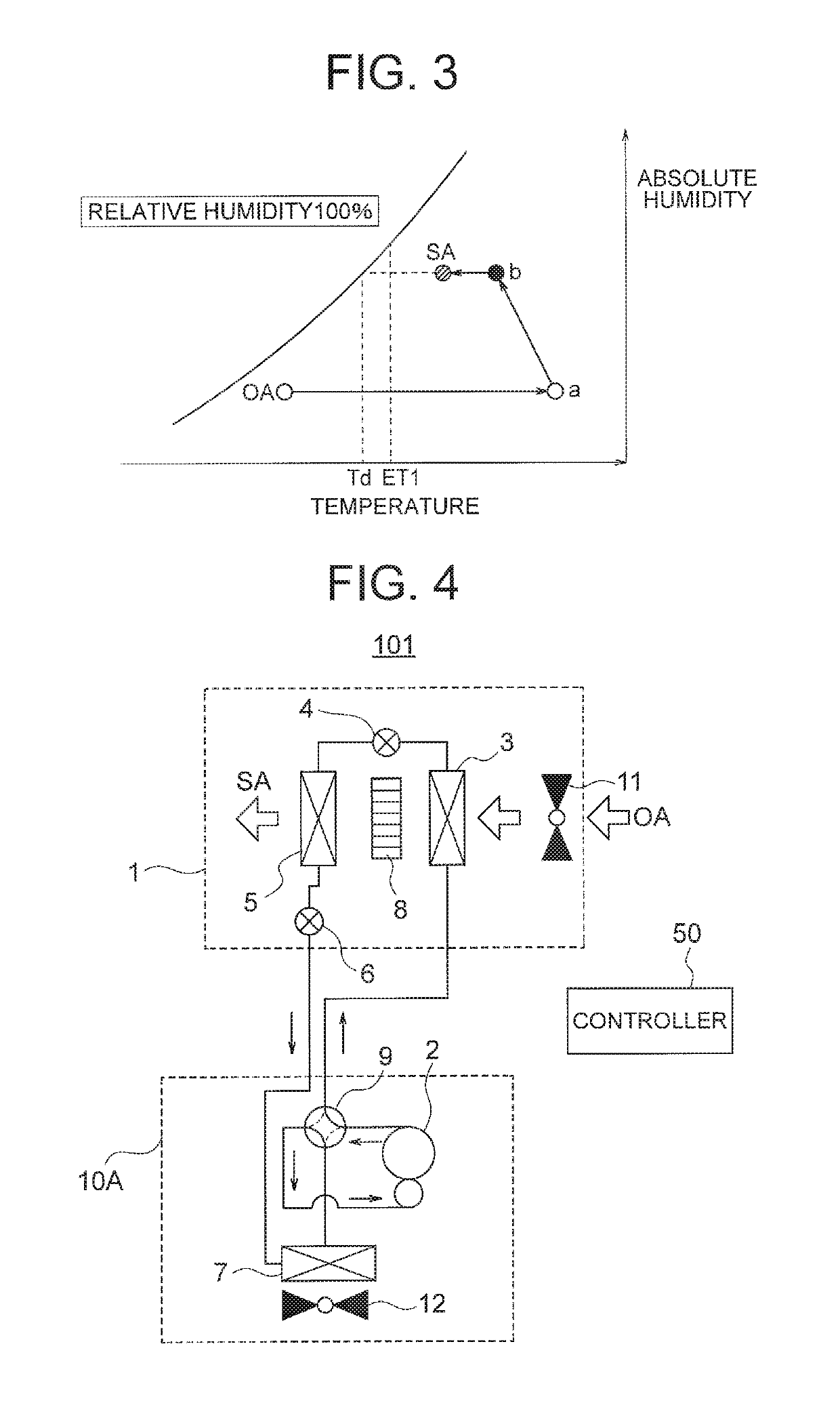
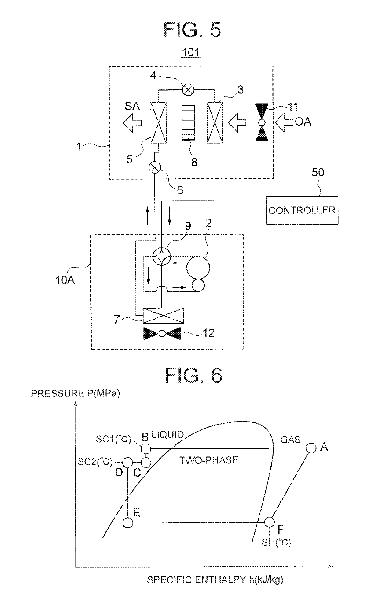
[0058]An air conditioning system 101 according to a second embodiment of the present invention will now be described. The above-described air conditioning system 100 of the first embodiment is configured to allow the refrigerant to circulate in one direction and perform the humidifying operation. In contrast, the air conditioning system 101 of the second embodiment is configured to be capable of switching a circulating direction of refrigerant and switching between a humidifying operation and a dehumidifying operation.

[0059]A configuration of the air conditioning system 101 of the second embodiment will now be described. FIG. 4 is a diagram illustrating the configuration of the air conditioning system 101 of the second embodiment and the flow of the refrigerant during the humidifying operation. In the air conditioning system 101 of the second embodiment, a four-way valve 9 as a flow path switching valve is provided on an outlet side of a compressor 2 of an outdoor unit 10A. The four...

third embodiment

[0084]An air conditioning system 102 according to a third embodiment of the present invention will now be described. The air conditioning system 102 of the third embodiment is obtained by adding a total heat exchanger 20 to the outside air processing unit 1 of the above-described air conditioning system 100 (101) of the first or second embodiment.

[0085]FIG. 7 is a diagram illustrating a configuration of the air conditioning system 102 of the third embodiment. An outside air processing unit 1A of the air conditioning system 102 includes a first airflow path 21 for introducing outdoor air (or air outside a room) OA, a second airflow path 22 for introducing indoor air (or air inside the room) RA, the total heat exchanger 20 that exchanges heat between the outdoor air OA and the indoor air RA, a third airflow path 23 for exhausting the indoor air RA flowing out of the total heat exchanger 20, and a fourth airflow path 24 for supplying the outdoor air OA flowing out of the total heat exc...


PUM


Abstract

An air conditioning system includes a compressor to compress refrigerant; a first heat exchanger to condense the compressed refrigerant into a supercooled liquid state; a first decompressor to decompress the condensed refrigerant; a second heat exchanger to cause the decompressed refrigerant to absorb heat; a second decompressor to decompress the heated refrigerant; a third heat exchanger to evaporate the decompressed refrigerant; and a blower fan to take in air from outside a room and blow the air to the first heat exchanger. The second heat exchanger is disposed downstream of the first heat exchanger in a blowing direction of the blower fan. A humidifier is disposed between the first heat exchanger and the second heat exchanger in the blowing direction. The air blown from the blower fan is heated by the first heat exchanger, humidified by the humidifier, cooled by the second heat exchanger, and supplied into the room.

Description

CROSS REFERENCE TO RELATED APPLICATION[0001]This application is a U.S. national stage application of International Patent Application No. PCT / JP2015 / 073307 filed on Aug. 20, 2015, the disclosure of which is incorporated herein by reference.TECHNICAL FIELD[0002]The present invention relates to an air conditioning system having a function of taking in air outside a room and supplying the air into the room.BACKGROUND ART[0003]Conventionally, there is known an air conditioning system including an outside air processing unit that takes in and humidifies air outside a room and supplies the air into the room. In such an air conditioning system, the humidification raises the temperature of the blown out air, leading to reduction in comfort in the room and increase in a cooling load.[0004]Thus, to make it possible to arbitrarily control the temperature of the blown out air, there is proposed a system that includes two independent refrigeration cycles including respective heat exchangers disp...

Claims


Application Information

Patent Timeline
Patent Type & Authority Patents(United States)
IPC IPC(8): F24F3/147F24F3/153F24F11/77F24F140/50
CPCF24F3/153F24F11/77F24F2140/50F24F11/89Y02B30/70
Inventor HORIE, HAYATOHAMADA, MAMORUTOYOSHIMA, MASAKI
Owner MITSUBISHI ELECTRIC CORP
Why Eureka
Try Eureka