Adaptive equalisation

a technology of equalization and adaptability, applied in the field of inspection apparatus, can solve the problem that the frequency response of the channel cable is not optimised for efficient data transmission, and achieve the effect of reducing the error signal

Active Publication Date: 2019-12-17
E V OFFSHORE
View PDF9 Cites 0 Cited by
  • Summary
  • Abstract
  • Description
  • Claims
  • Application Information

AI Technical Summary

Benefits of technology

[0011]This invention is designed for use in transmission of data between downhole module in a wellbore and a controlling module at the surface. The invention provides an apparatus for receiving data signals from a telemetry module comprising first and second adaptive equalisers, and in which in a first modulation mode the coefficients of the first adaptive equaliser are updated until an error signal falls below a predetermined threshold and in a second modulation mode the coefficients of the first adaptive equaliser are locked and coefficients of the second adaptive equaliser are updated to continually minimise an error signal in which the number of bits encoded by the symbols of the first signal in an initial modulation mode is fewer than the number of bits encoded by the symbols of the second signal in a subsequent modulation mode.
[0017]According to a further aspect of the invention there is provided an apparatus for receiving data signals from a telemetry module comprising: a first adaptive equaliser for receiving a signal transmitted via a channel in which the received signal differs from the transmitted signal due to channel distortion and / or noise, the signal comprising a sequence of symbols encoded by inphase and quadrature components; the first adaptive equaliser comprising: a first filter for filtering a portion of the received signal using a first filter having a plurality of first filter coefficients; a first slicer for determining the likely inphase and quadrature components of the first transmitted signal; a first error calculator for determining a first error signal in dependence upon the difference between the likely inphase and quadrature components and the received inphase and quadrature components; and a first coefficient updater for updating the first filter coefficients to reduce said first error signal when the received signal is encoded by the initial modulation and until the average first error signal is less than a predetermined threshold; and a second filter for filtering a portion of the a first filtered signal received from the first filter using a second filter having a plurality of second filter coefficients; a second slicer for determining the likely inphase and quadrature components of the second transmitted signal; a second error calculator for determining a second error signal in dependence upon the difference between the likely inphase and quadrature components and the received inphase and quadrature components; and a second coefficient updater for updating the second filter coefficients to reduce said second error signal.

Problems solved by technology

The wireline cable is not primarily designed as a communications channel for efficiently transmitting modulated data signals and therefore the channel frequency response of the cable is not optimised for efficient data transmission.

Method used


Image

  • Adaptive equalisation
  • Adaptive equalisation
  • Adaptive equalisation

Examples


Embodiment Construction

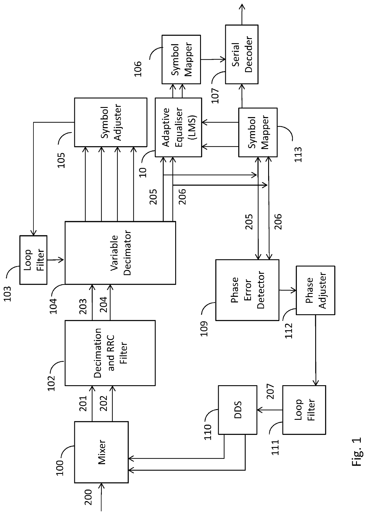
[0028]FIG. 1 is a block diagram showing a QAM demodulator with an adaptive equaliser.

[0029]A mixer 100 receives an input signal 200 and generates inphase signal 201 and quadrature signal 202.

[0030]Signals 201, 202 are down converted by a decimation and RRC filter 102 to generate down converted inphase signal 203 and down converted quadrature signal 204.

[0031]A variable decimator 104, a symbol adjuster 105 and a loop filter 103 are used to detect the symbol timing error and sample the symbol at the ideal point to generate inphase symbol sample 205 and quadrature symbol sample 206.

[0032]Symbol samples 205, 206 are processed by a phase error detector 109, a phase adjuster 102 and a loop filter 111 to determine a correction value 207 for use by a digital direct synthesiser (DDS) 110. The DDS 110 generates a carrier frequency to feed to the mixer 100.

[0033]The symbol sample 205, 206 are processed by a symbol mapper 113 prior and equalised by adaptive equaliser 10 (which will be described...


PUM


Abstract

This invention is designed for use in transmission of data between downhole module in a wellbore and a controlling module at the surface. The invention provides an apparatus for receiving data signals from a telemetry module comprising first and second adaptive equalisers, and in which in a first modulation mode the coefficients of the first adaptive equaliser are updated until an error signal falls below a predetermined threshold and in a second modulation mode the coefficients of the first adaptive equaliser are locked and coefficients of the second adaptive equaliser are updated to continually minimise an error signal in which the number of bits encoded by the symbols of the first signal in an initial modulation mode is fewer than the number of bits encoded by the symbols of the second signal in a subsequent modulation mode.

Description

CROSS-REFERENCE TO RELATED APPLICATIONS[0001]This patent application claims the benefit of and priority to UK Patent Application No. 1701713.8, filed on Feb. 2, 2017. The disclosure of this patent application is herein incorporated by reference in its entirety.BACKGROUNDa. Field of the Invention[0002]The present invention relates to inspection apparatus for use in wellbores in the oil and gas industries. In particular the invention relates in general to the field of transmission of data between downhole module in a wellbore and a controlling module at the surface.b. Related Art[0003]Accurate collection of geophysical data is a key to successful exploration and production in oil and gas industries. Based on data collected in a wellbore it is possible to determine whether a well is likely to be productive, and decisions can be made such as whether to drill additional wells near an existing well or whether to abandon a well as being unproductive.[0004]Collecting wellbore data is known ...

Claims


Application Information

Patent Timeline
Patent Type & Authority Patents(United States)
IPC IPC(8): E21B47/12H04L27/148H04L25/03H04L27/34H03H21/00
CPCH04L27/148H04L27/34H04L25/03885H04L25/0305H04L25/03019E21B47/12H03H2021/0092H04L2025/03636H04L25/03057H04L27/38
Inventor EADALA, SUMANTHTHURSBY, JONATHAN
Owner E V OFFSHORE
Why Eureka
Try Eureka