Microelectromechanical inertial sensor including a substrate and an electromechanical structure situated on the substrate

a micro-electromechanical and inertial sensor technology, applied in the direction of speed measurement using gyroscopic effects, instruments, surveying and navigation, etc., can solve the problem of non-linearity of above linear relationship, fluctuations impair and partially considerable parasitic capacitance always exist, so as to improve the linearity of sensor characteristic curve

Active Publication Date: 2021-09-30
ROBERT BOSCH GMBH
View PDF23 Cites 0 Cited by
  • Summary
  • Abstract
  • Description
  • Claims
  • Application Information

AI Technical Summary

Benefits of technology

[0014]The above descriptions relate to the case of an inertial sensor including a mass oscillator and at least three associated electrodes. The capacitive compensation structures according to the present i

Problems solved by technology

In a practical implementation of this measuring principle, however, partially considerable parasitic capacitances always exist, for example between the mass electrode and the substrate.
If the electrodes are now connected to an electrical potential, an additional charge shift occurs, due to the parasitic capacitances, which disrupts the charge balance between the two electrode pairs, and thus renders the above linear relationship non-linear.
The process fluctu

Method used


Image

  • Microelectromechanical inertial sensor including a substrate and an electromechanical structure situated on the substrate

Examples


Embodiment Construction

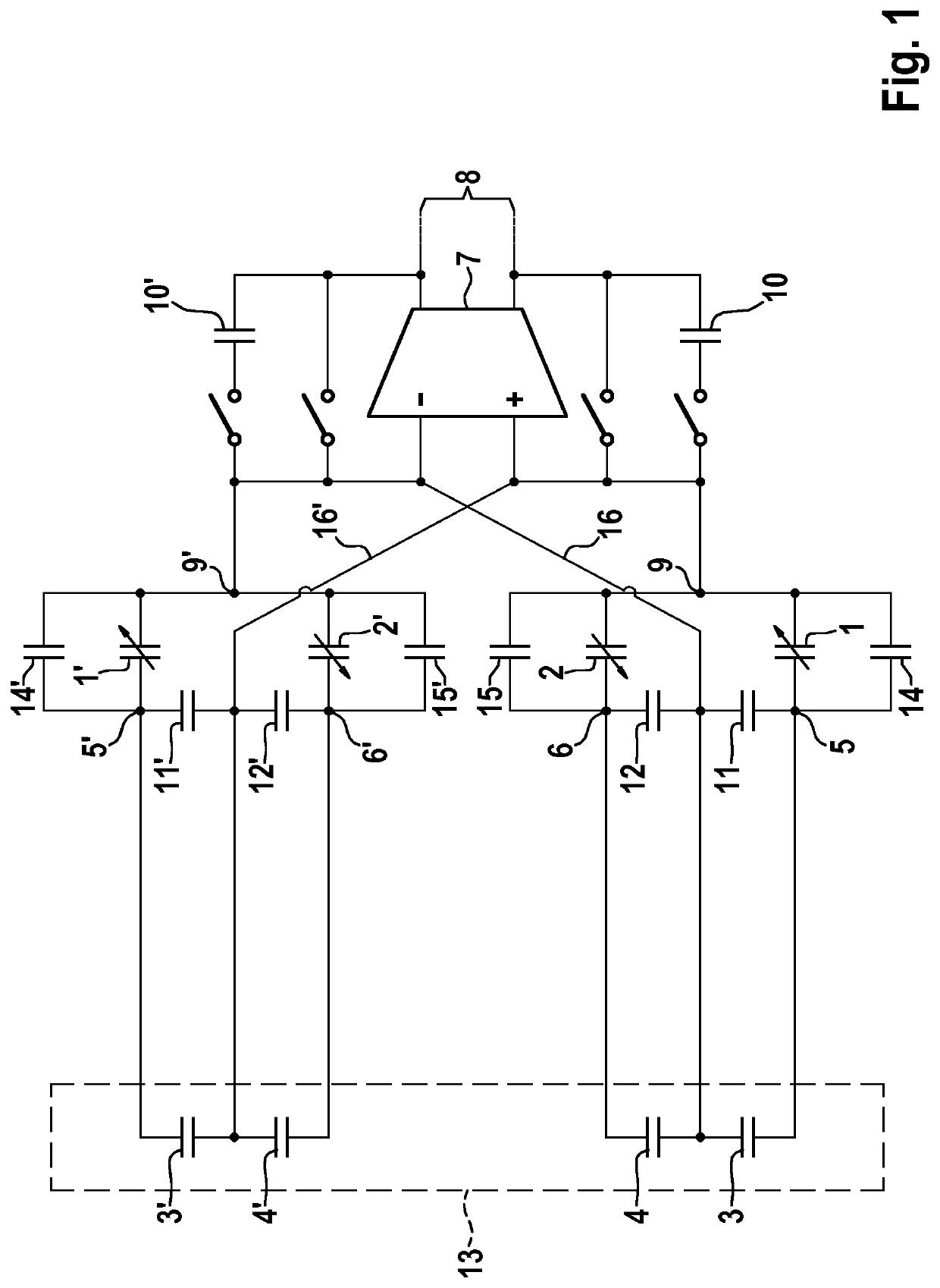
[0018]FIG. 1 shows the schematic circuit diagram of a possible implementation of a capacitance-to-voltage transformer for an inertial sensor including capacitive compensation structures. In this specific embodiment, the sensor core includes two mass oscillators, each mass oscillator including a mass electrode (first electrode), which is situated between two substrate electrodes (second and third electrodes). The two mass oscillators and the associated electrodes are identical in terms of the design, however electrical potentials having opposite polarities are applied thereto. Depending on the deflection of the first mass oscillator and the mass electrode connected thereto, a first capacitance 1 is present between the first substrate electrode and the mass electrode, and a second capacitance 2 is present between the second substrate electrode and the mass electrode.

[0019]In the case of a perfect charge equalization between the two electrode pairs, the output voltage is linearly depen...


PUM


Abstract

A microelectromechanical inertial sensor including a substrate and an electromechanical structure situated on the substrate.

Description

FIELD[0001]The present invention is directed to a microelectromechanical inertial sensor.BACKGROUND INFORMATION[0002]Various specific embodiments of microelectromechanical inertial sensors in the related art are conventional. The measuring principle of such sensors is based on the inertial forces which occur during a linear acceleration or rotation being detectable by the deflection of a seismic mass. To convert the deflection into an electrical signal, an electrode (mass electrode) connected to the resiliently mounted seismic mass (mass oscillator), for example, is situated between two electrodes fixed to a substrate (substrate electrodes). The deflection of the mass oscillator results in a change in distance of the first electrode pair (i.e., between the first substrate electrode and the mass electrode) and a change in distance of the second electrode pair (second substrate electrode and mass electrode), and thus in a change in the capacitances C1 and C2 of the two electrode pairs...

Claims


Application Information

Patent Timeline
IPC IPC(8): G01P15/125G01C19/5776
CPCG01P15/125G01C19/5776
Inventor KIESEL, STEFANBOESER, TOBIAS
Owner ROBERT BOSCH GMBH
Why Eureka
Try Eureka