Apparatus and method for providing a supply voltage to a device under test using a compensation signal injection

Active Publication Date: 2020-01-09
ADVANTEST CORP
View PDF0 Cites 1 Cited by
  • Summary
  • Abstract
  • Description
  • Claims
  • Application Information

AI Technical Summary

Benefits of technology

[0033]In embodiments the apparatus is configured to provide the control signal to the regulator based on an error signal. The error signal is based on a difference between a measured voltage of the device under test port and the information about a desired voltage. Using the described error signal the apparatus can flexibly adjust the provided voltage by the controlled source in order to minimize the error signal when the error signal characterizes a deviation from the device under test port voltage to a desired voltage.
[0034]In embodiments the regulator is configured to provide the control signal using an integration of the error signal. Using an integration of the error signal brings stability to the control as large errors due to noisy m

Problems solved by technology

However, when switching from one current measurement range to another measurement range, for example Range 1 to Range 2 in FIG. 14, a glitch is generated at a device under test port.
This means that they do not operate instantaneously, i.e., their change of resistance is “slow”.
However, it has been found that a control of the loop has to be faster than a glitch.
However, it has been found that a complete cancellation is difficult as a full control over the switch resistance is difficult.
The described apparatus is based on the insight that a control of the voltage at the device under test port may not be fast enough to compensate a glitch when changing a state of the switchable resistor when performed only using a feedback from the device under test port.
In particular, when a switch state of the switchable resistor is changed, an effective resistance of the switchable resistor is changed leading to a changed voltage drop across the switchable resistor.
The changed voltage drop propagates to (or

Method used


Image

  • Apparatus and method for providing a supply voltage to a device under test using a compensation signal injection
  • Apparatus and method for providing a supply voltage to a device under test using a compensation signal injection
  • Apparatus and method for providing a supply voltage to a device under test using a compensation signal injection

Examples


Example

[0053]In the following same references are used throughout various figures to indicate similar or identical properties of the referenced items.

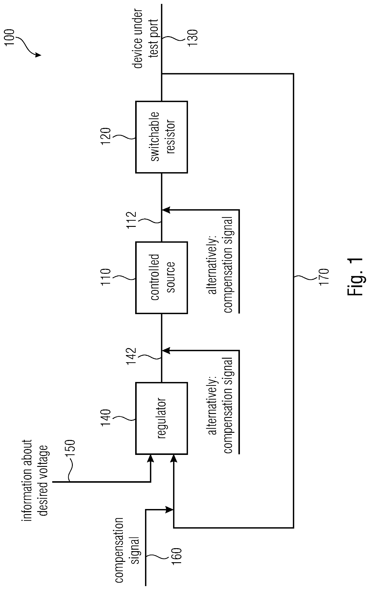
[0054]FIG. 1 shows a block diagram of an apparatus 100 for providing a supply voltage to a device under test according to embodiments of the invention. The apparatus 100 comprises a controlled source 110, a switchable resistor 120, a regulator 140 and a device under test port 130. The regulator 140, the controlled source 110 and the switchable resistor 120 are arranged in a control loop 170.

[0055]The control loop 170 feeds back a measurement of a voltage at the device under test port 130 to the regulator 140. Before entering the regulator 140 a compensation signal 160 is injected into the control loop (wherein the compensation signal may also be injected between the regulator 140 and the controlled source 110 or between the controlled source 110 and the switchable resistor 120). Based on the information obtained through the control loop and a...


PUM


Abstract

An apparatus for providing a supply voltage to a device under test includes: a controlled source; a switchable resistor circuited between the output of the controlled source and a dut port, having a comparatively smaller first resistance in a first switch state and a second resistance in a second switch state; a regulator that provides a control signal to the controlled source, to regulate a voltage to be provided to the dut. The apparatus changes a switch state of the switchable resistor while a voltage is provided to the dut via the switchable resistor. The apparatus injects a compensation signal into a control loop including the regulator, the controlled source and the switchable resistor, to thereby cause a change of the voltage provided by the controlled source, to at least partially compensate a change of a voltage drop across the switchable resistor.

Description

CROSS-REFERENCE TO RELATED APPLICATION[0001]This application is a continuation of copending International Application No. PCT / EP2017 / 057688, filed Mar. 31, 2017, which is incorporated herein by reference in its entirety.[0002]Embodiments of the present invention relate to providing a supply voltage to a device under test.BACKGROUND OF THE INVENTION[0003]For conventional concepts a digital loop is used to control an output voltage or a device under test voltage. FIG. 14 shows a block diagram of an apparatus for providing a supply voltage to a device under test with two current measurement ranges. However, when switching from one current measurement range to another measurement range, for example Range 1 to Range 2 in FIG. 14, a glitch is generated at a device under test port. Furthermore, FIG. 15 shows a block diagram of an apparatus according to another conventional approach for providing a supply voltage to a device under test. The apparatus in FIG. 15 has switches which are operat...

Claims


Application Information

Patent Timeline
IPC IPC(8): G01R31/28G05F1/46
CPCG05F1/46G01R31/2832G01R31/2879G01R31/31721G05F1/575
Inventor MÜCKE, MARTINHORVATH, PETER
Owner ADVANTEST CORP
Why Eureka
Try Eureka