Method and device for controlling power semiconductor switches connected in parallel

a technology of power semiconductor switches and devices, applied in electric devices, pulse techniques, transportation and packaging, etc., can solve the problems of power semiconductor switches being damaged irreversibly, aging more rapidly, and thus failing more rapidly, and achieves uniform aging, high operating safety, and safe operation of vehicles.

Active Publication Date: 2019-12-31
ROBERT BOSCH GMBH
View PDF14 Cites 2 Cited by
  • Summary
  • Abstract
  • Description
  • Claims
  • Application Information

AI Technical Summary

Benefits of technology

[0007]Consequently, a method is advantageously provided which makes it possible for power semiconductor switches connected in parallel to be switched on deliberately at different points in time. This makes it possible for switch-on, switch-off and current-conducting losses not to be distributed arbitrarily over one or a few of the power semiconductor switches connected in parallel, but rather, by means of mutually independent control, for example by means of overlapping control, of the different power semiconductor switches, to be distributed in a targeted manner and, if appropriate, uniformly among the power semiconductor switches connected in parallel. In particular, by means of selection and alternation of the power semiconductors that close or open first, the switch-on and switch-off losses can be distributed in a targeted manner among the individual power semiconductors. By means of varying the temporal duration of the states, in particular of the state close, of the individual control signals, the current-conducting losses can be varied. A method is thus created which enables more uniform distribution of the power among power semiconductor switches connected in parallel during the operation thereof, even if the power semiconductor switches, on account of their component tolerances or their different dimensioning, react to a control signal at different speeds and with different sensitivities. Operation of a parallel circuit comprising power semiconductor switches for example from different batches or wafers or having different structural sizes or powers without singular overloading of a power semiconductor switch, in conjunction with optimum utilization of the performance of all the power semiconductor switches, is thus made possible.
[0049]An electrical system is advantageously provided which enables the uniform aging of power semiconductor switches connected in parallel and thus safe operation of the vehicle.

Problems solved by technology

Upper limits of current are predefined for said power semiconductor switches, the power semiconductor switches being damaged irreversibly in the event of said upper limits being exceeded.
Individual power semiconductor switches are thermally loaded to a greater extent than others, age more rapidly and thus fail more rapidly.

Method used


Image

  • Method and device for controlling power semiconductor switches connected in parallel
  • Method and device for controlling power semiconductor switches connected in parallel

Examples


Embodiment Construction

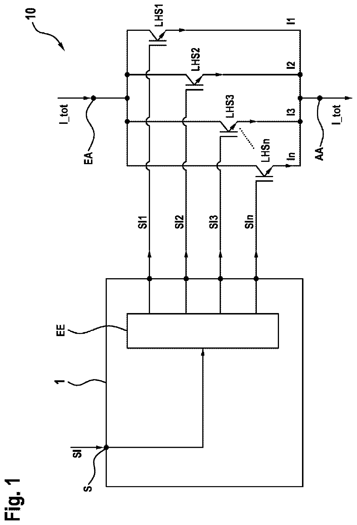
[0058]FIG. 1 shows an electrical system 10 in a schematic illustration. A total current I_tot is fed to the electrical system 10 at an input terminal EA. Power semiconductor switches LHS1 . . . LHSn connected in parallel are connected to the input terminal EA on the input side and to the output terminal AA on the output side. The total current I_tot is divided among the power semiconductor switches which are closed, that is to say have the state close. Accordingly, the sum of the individual currents I1 . . . In through the respective power semiconductor LHS1 . . . LHSn connected in parallel always corresponds to the total current I_tot. The total current I_tot is conducted away via the output terminal AA. The power semiconductor switches LHS1 . . . LHSn connected in parallel serve both for current carrying and interruption of the current flow from the input terminal EA to the output terminal AA. The power semiconductor switches LHS1 . . . LHSn connected in parallel each have a gate ...


PUM


Abstract

The invention relates to a method (200) and a control device (I) for controlling at least two power semiconductor switches (LHS1 . . . LHSn) connected in parallel for switching a total current (I_ges). The at least two power semiconductor switches (LHS1 . . . LHSn) connected in parallel each have a gate terminal for controlling the respective power semiconductor switch (LHS1 . . . LHS2). An input terminal (EA) for feeding the total current (I_ges), an output terminal (AA) for discharging the total current (I_ges), and a joint control terminal (S) for receiving a joint control signal (SI) that has the state ‘disconnect’ or ‘connect’ are provided. The at least two power semiconductor switches (LHS1 . . . LHSn) connected in parallel are connected to the input terminal (EA) at an input end and to the output terminal (AA) at the output end.

Description

BACKGROUND OF THE INVENTION[0001]The invention relates to a method and a control device for controlling power semiconductor switches connected in parallel. Furthermore, the invention relates to an electrical system comprising the control device, a computer program for carrying out said method, and an electronic storage medium.[0002]Inverters are usually used for operating electrical drives, said inverters converting the electrical energy from a DC voltage source, e.g. a battery, into an AC voltage, in order to supply an electrical machine, e.g. an asynchronous machine, with AC voltage or AC current. The inverter has so-called half-bridges for this purpose. Said half-bridges have power semiconductor switches, by means of which the DC current and the DC voltage are switched in a clocked fashion, such that an AC voltage and an AC current arise at the output terminals of the inverter. Upper limits of current are predefined for said power semiconductor switches, the power semiconductor s...

Claims


Application Information

Patent Timeline
Patent Type & Authority Patents(United States)
IPC IPC(8): B60L1/00B60L3/00H02G3/00H03K17/16H03K17/12H02M1/088B60R16/03B60R16/02
CPCH03K17/127H02M1/088H03K17/167B60R16/03B60R16/02
Inventor BUTZMANN, STEFANECKERT, BERNDTAUFER, PETER
Owner ROBERT BOSCH GMBH
Why Eureka
Try Eureka