Large-plane efficient precision electrolytic mechanical combined machining tool and method

An electrolytic machine and composite machining technology, applied in the field of electrolytic machining, can solve the problems of electric field distribution and uneven distribution of electricity on the bottom surface of processing, and achieve the effects of not easy to burn, uniform distribution of electricity, and efficient machining accuracy.

Inactive Publication Date: 2021-04-16
NANJING UNIV OF AERONAUTICS & ASTRONAUTICS
View PDF3 Cites 0 Cited by
  • Summary
  • Abstract
  • Description
  • Claims
  • Application Information

AI Technical Summary

Problems solved by technology

From the aspect of optimizing the electric field, Niu et al. adopted the solution of insulating the bottom of the tool to reduce the power transmission from the cathode of the tool to the middle area of ​​the groove area. However, because the bottom is insulated, only other tools can be replaced during finishing (Niu, Shen , NingsongQu, and Hansong Li. "Investigation of electrochemical mill-grinding using abrasive tools with bottom insulation." The International Journal of Advanced Manufacturing Technology 97.1-4 (2018): 1371-1382.); The way of opening holes at the bottom changes the flow field environment at the bottom of the tool, which in turn affects the distribution of the electric field on the bottom surface of the machine (Yue, Xiaokang, et al. "Improving the machined bottom surface inelectrochemical mill-grinding by adjusting the electrolyte flow field."Journal of Materials Processing Technology 276 (2020): 116413.)
The above studies have made great progress. However, these solutions are all optimization measures taken at the bottom of the round rod-shaped electrode, and cannot fundamentally eliminate the phenomenon of uneven power distribution caused by the electrode geometry.

Method used


Image

  • Large-plane efficient precision electrolytic mechanical combined machining tool and method
  • Large-plane efficient precision electrolytic mechanical combined machining tool and method
  • Large-plane efficient precision electrolytic mechanical combined machining tool and method

Examples


Embodiment Construction

[0032] Combine below Figure 1 to Figure 5 , to further describe the specific implementation of the present invention - "a large-scale high-efficiency precision electrolytic mechanical composite processing tool and method".

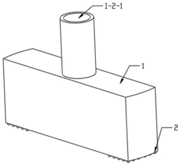
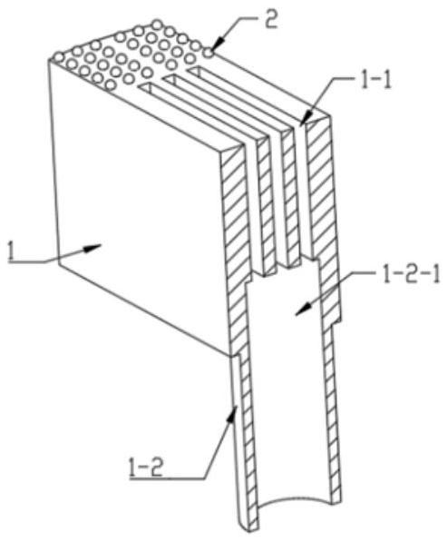
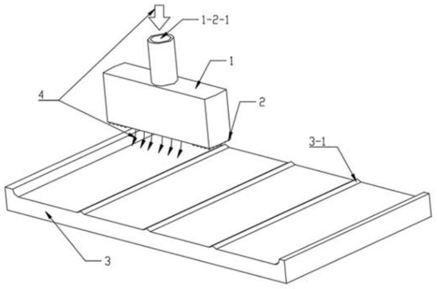
[0033] A large-plane high-efficiency precision electrolytic mechanical composite processing tool, including a cuboid tool cathode body 1 with a rectangular electrolyte nozzle 1-1, abrasive grains 2, and a clamp with a central liquid inlet hole 1-2-1 handle 1-2; the electrolyte nozzles 1-1 are arranged side by side at equal intervals on the lower end surface of the cathode body 1; the clamping handle 1-2 is arranged at the geometric center of the largest circumscribed circle of the tool cathode body 1; the The liquid inlet hole 1-2-1 is arranged at the geometric center of the end face of the clamping handle 1-2; the liquid inlet hole 1-2-1 communicates with the electrolyte nozzle 1-1, and the abrasive grains 2 are The center line of the long side of the e...


PUM

PropertyMeasurementUnit
lengthaaaaaaaaaa
widthaaaaaaaaaa
diameteraaaaaaaaaa

Abstract

The invention discloses a large-plane efficient precision electrolytic mechanical combined machining tool and method, and relates to the technical field of electrolytic machining. The tool is characterized by comprising a cuboid-shaped tool cathode body with rectangular electrolyte nozzles, abrasive particles and a clamping handle with a central liquid inlet hole. The electrolyte nozzles (1-1) are arranged on the lower end face of the tool cathode body in parallel at equal intervals. The clamping handle is arranged at the geometric center of the maximum circumcircle of the tool cathode body. The liquid inlet hole is formed in the geometric center of the end face of the clamping handle. The liquid inlet hole is communicated with the electrolyte nozzles, and the abrasive particles are symmetrically arranged on the end face of the tool cathode body about the center line of the long sides of the electrolyte nozzles. According to the large-plane efficient precision electrolytic mechanical combined machining tool and method, in the tool cathode feeding process, the electric quantity distribution in a machining area on the surface of a workpiece is uniformized better, so that the electrolytic machining precision is high, and the comprehensive machining time is short.

Description

technical field [0001] The invention relates to the technical field of electrolytic machining, in particular to a large-plane high-efficiency precision electrolytic mechanical composite machining tool and method. Background technique [0002] The forming and preparation of difficult-to-machine materials such as high-temperature alloys, titanium alloys, and titanium-based composite materials are the basic elements for these products to achieve some extreme performance in aerospace weapons and equipment. High hardness, high strength, and poor thermal conductivity are often the salient features of these materials, which make their forming-forming-forming-forming manufactures face many challenges. For the processing and forming of aerospace parts with large planes and large margins removed, the main processing methods are machining, EDM, electrolytic machining, and electrolytic composite machining. [0003] Compared with the "head-to-head" machining of mechanical processing, th...

Claims


Application Information

Patent Timeline
Patent Type & Authority Applications(China)
IPC IPC(8): B23H5/08B23H5/14
Inventor 曲宁松张峻中沈志豪
Owner NANJING UNIV OF AERONAUTICS & ASTRONAUTICS
Why Eureka
Try Eureka