

System and method for the diagnosis, evaluation and prediction of leakages in different hydraulic circuits, quickly and safely for the operator
a technology of hydraulic circuit and system, applied in the direction of braking system, force/torque/work measurement apparatus, instruments, etc., can solve the problems of reducing the availability of production processes, and affecting the quality of production
Active Publication Date: 2020-01-07
SOC RAMIREZ E HIJO LTDA
View PDF4 Cites 0 Cited by
- Summary
- Abstract
- Description
- Claims
- Application Information
AI Technical Summary
Benefits of technology
The patent describes a system and method for diagnosing, evaluating, and predicting leaks in hydraulic circuits. The system is portable, fast, and safe for operators. It uses pressure meters to collect data from each line and a computer to analyze and control the system. The system allows for parallel diagnostic routines for both high and low pressure systems. Overall, the technology provides a quick and reliable way to diagnose and prevent leaks in hydraulic circuits.
Problems solved by technology
Nowadays it is common that, in the face of operating problems, the repair of systems, such as brakes, is carried out without prior diagnosis that includes pre-load testing of the set of final drive components, such as the wet brake (oil-cooled disc brakes), leading to loss of time in the assembly and disassembly of components, and even, causing greater damage to both the component and the machinery.
When companies carry out maintenance and repairs without considering evaluations and diagnoses that enable to reduce the frequency of corrective maintenance, the equipment is halted, causing their availability in production processes to decrease, in addition to incurring costs associated with losses in expensive components and spare parts.
In general, the manufacturers of machinery and equipment that are typically used in mining operations and the contracting companies that operate or perform their maintenance, proceed to make repairs without taking into account the actual state of the hydraulic system of the machinery due to the lack of a system and method that allows the fast and efficient detection of internal leakage of hydraulic oil, wear of materials, deterioration of different hydraulic actuators and systems, such as failures in final drive reductions or stub hub bearings, among others, that produce contamination and loss of oils.
Whether oil flows through the orifice, it will hypothetically show that there is indeed internal leakage between the different hydraulic systems involved, but this entails slow tests and low reliability of the actual state of the hydraulic system.
Likewise, spare parts are replaced unnecessarily.
The current method is not effective, since the systems pressure is not adequate to cause internal leakage, because the engine is at low RPM, not in normal running condition, and the oil is not at its working temperature, presenting higher viscosity and slower flow rate, which does not allow a good diagnosis.
As an example, in mining, the high cost of repairing or changing a final drive and wet brake together is approximately USD 130,000, owing, among other factors, to the time spent between 4 and 8 hours.
In view of this background there is a need for a diagnostic system and method to evaluate and predict failures in oil-hydraulic systems of different types of machinery without requiring to start the hydraulic pumps or the engines of the equipment to be evaluated, since getting started the hydraulic pumps or the motors for the diagnosis generates high costs, and can also cause accidents to maintenance personnel when the components of the hydraulic system to be evaluated are damaged.
But this system is not designed to evaluate leaks of low pressure hydraulic circuits, for example between 0 to 6.89 bar, so it is unsafe for an operator trying to apply it to said hydraulic circuits, since a rupture of a hose may cause serious damage to the operators health and even death; this is because in addition to the operating pressure in the pump, the pressure is intensified by a set of cylinders and valves.
Another document disclosing the diagnosis of internal leakage in a hydraulic system is JP2141636, which relates to early detection of internal leakage, wherein leakage evaluation is performed by measuring the loading times relative to a reference time or when the accumulated time of the no-load states do not reach the reference time; but this document does not solve the problem of the evaluation of hydraulic circuits of low and high pressure with a single system.
However, this technology does not solve the problem of testing in low pressure and high pressure hydraulic circuits with an electronic control system and operating safely for the operator, without requiring high pressure or requiring high pressure pump of the hydraulic system to operate.
In the prior art document it is not possible to handle pressures or independent flows, which involves greater risks for the operator.
Method used
View moreImage
Smart ImageViewing Examples


Examples
example of use no 7
and Diagnosis of Oil
[0099]Diagnosis and evaluation of oil contamination through an equipment inserted in the same line of the machinery.
Login to View More PUM
| Property | Measurement | Unit |
|---|---|---|
| time | aaaaa | aaaaa |
| time | aaaaa | aaaaa |
| time | aaaaa | aaaaa |
Abstract
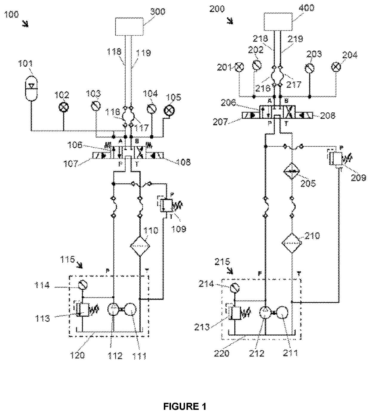
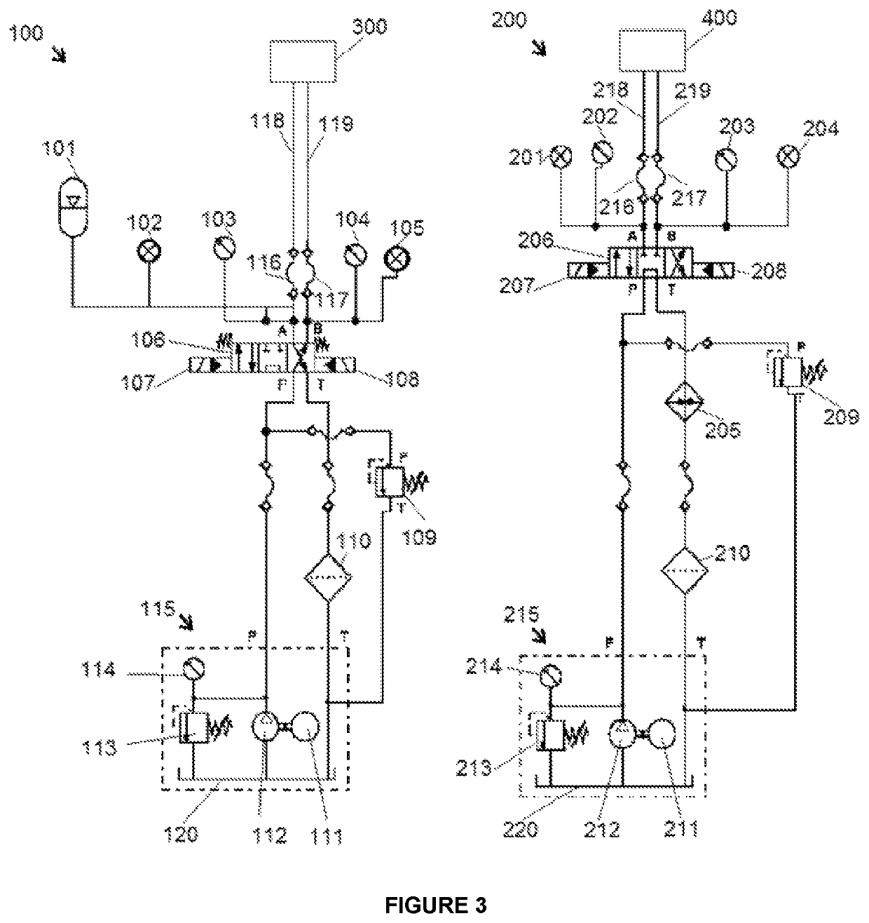
Transportable system for the diagnosis, evaluation and prediction of leakages in hydraulic circuits of low pressure between 0 to 7 bar and of high pressure from 0 to 170 bar, quickly and safely for the operator is provided having a first independent circuit of high pressure and low flow and a second independent circuit of low pressure and high flow wherein the first independent circuit comprises: a first pressure subsystem, which delivers pressure to a first 4 / 3 valve with ports A, B, P and T, which is actuated by first solenoids, to deliver pressure to a first coupling A or to a first coupling B, in fluid communication with the ports A and B of the first 4 / 3 valve respectively a computer arranged to control the pressure of each pressure subsystem and associated method.
Description
CROSS REFERENCE TO RELATED APPLICATION[0001]This Application claims the priority of Chilean Patent Application No. 201601969 filed on Aug. 4, 2016, which is incorporated herein by reference.FIELD OF THE INVENTION[0002]The present invention relates to the oil-hydraulic machinery industry. In particular, the present invention relates to a diagnostic system and method to evaluate and predict failures in oil-hydraulic systems of different types of machinery, wherein the hydraulic systems may be final drive components, rotary unions, circuits in machinery, and halted mobile equipment. It should be mentioned that as final drive components are understood hopper lift cylinders, brake packs, actuating and central articulation cylinders of loaders, refrigeration systems or heat exchangers, cylinders, valves, coolers, among others.DESCRIPTION OF THE RELATED ART[0003]Nowadays it is common that, in the face of operating problems, the repair of systems, such as brakes, is carried out without prio...
Claims
Login to View More Application Information
Patent Timeline
 Patent Type & AuthorityPatents(United States)
IPC IPC(8): B60T17/22B60T8/26G01M3/28F16D66/02B60T13/68F16D66/00G01L5/28
CPCG01M3/2815B60T8/266B60T17/22B60T17/222F16D66/021F16D2066/005B60T13/686G01L5/28
InventorRAMIREZ LEANO, MIGUEL ANGELRAMIREZ LEANO, CARLOS CRISTIANRAMIREZ ORTIZ, CARLOS ALBERTO
OwnerSOC RAMIREZ E HIJO LTDA