
Plating method

a plating method and a technology of a plated bulge, applied in the direction of application, chemical coating, liquid/solution decomposition, etc., can solve the problems of difficult to easily change the shape of the embossed object surface, and the above-described methods are not suitable for small lot production of a variety of products, so as to suppress internal stress and improve the appearance of the plated bulge. , the effect of improving the appearan

Active Publication Date: 2020-01-07
MIMAKI ENG
View PDF4 Cites 0 Cited by
  • Summary
  • Abstract
  • Description
  • Claims
  • Application Information

AI Technical Summary

Benefits of technology

This method allows for easy formation of various decorative patterns and improved decorativeness by creating contrasting gloss levels and surface textures on objects, while ensuring the durability and adhesion of the coating layer, suitable for small lot production and diverse product designs.

Problems solved by technology

In this case, since hubbly plates are used in embossing processes, it is difficult to easily change shapes to be embossed on the surfaces of objects.
Therefore, the above-described methods are not suitable for small lot production of a variety of products.

Method used


Image

  • Plating method
  • Plating method
  • Plating method

Examples


first embodiment

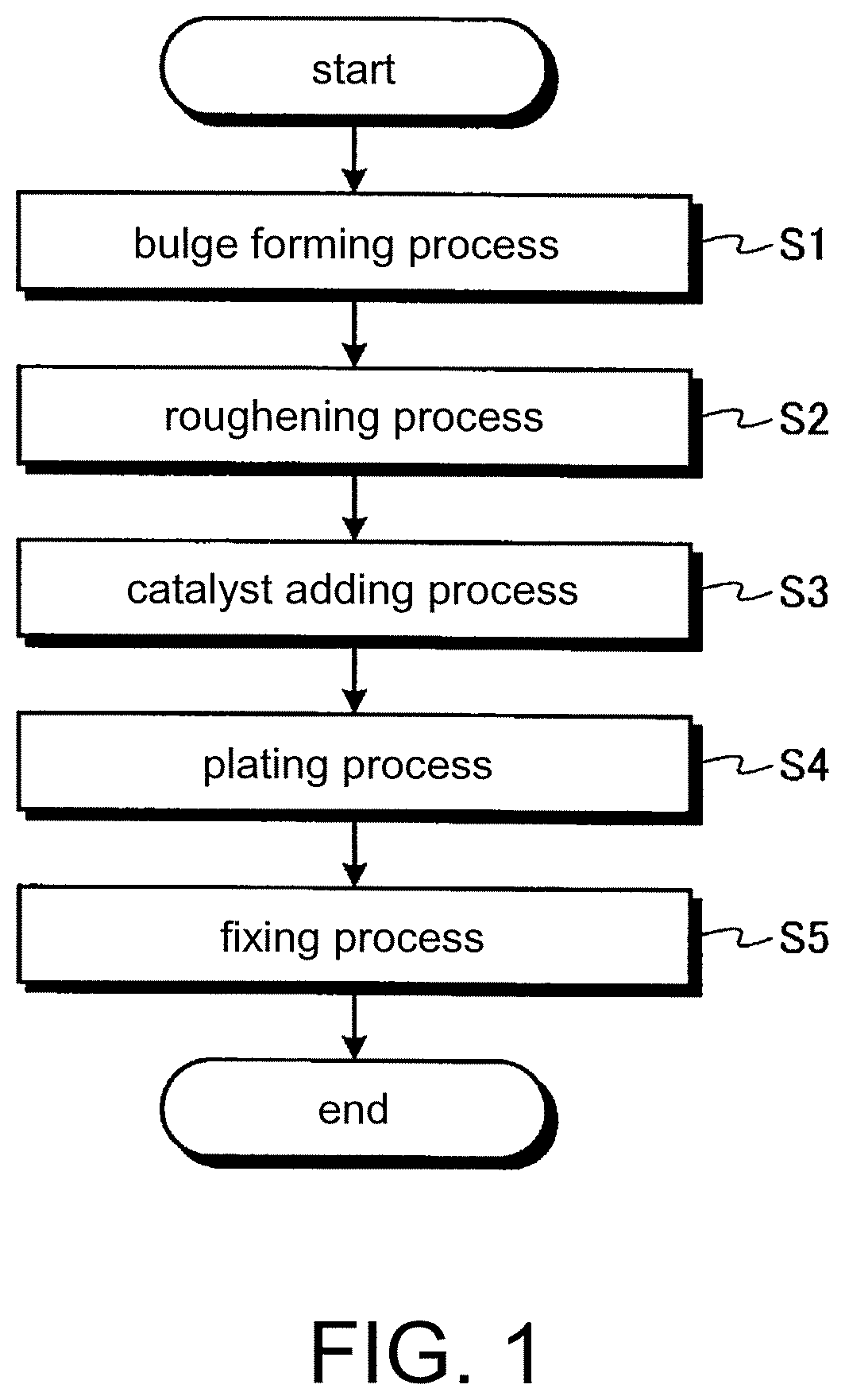
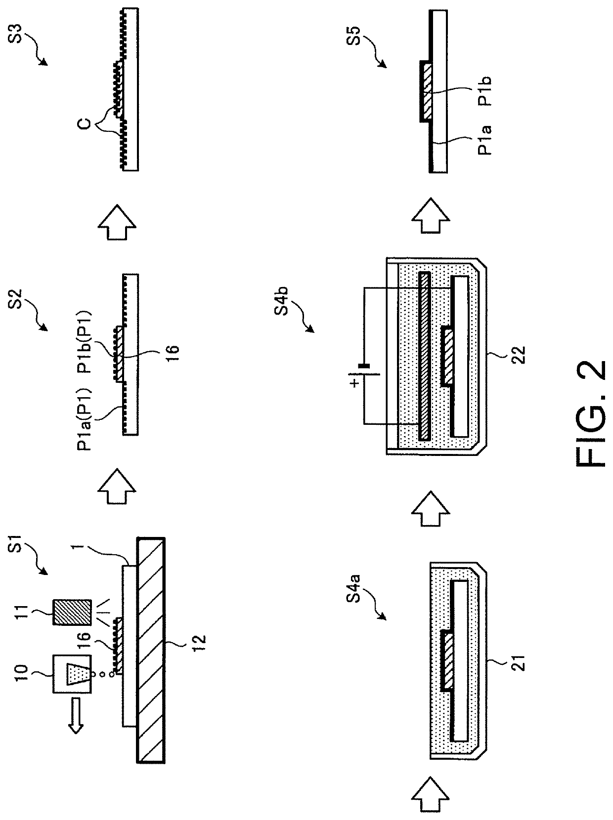
[0028]A plating method according to a first embodiment forms bulges on objects to be plated by inkjet printing, and performs a plating process on the objects having the bulges. Hereinafter, the plating method will be described with reference to FIGS. 1 and 2. FIG. 1 is a flow chart illustrating the plating method according to the first embodiment. FIG. 2 is an explanatory view illustrating the plating method according to the first embodiment.

[0029]Prior to a description of the plating method, first, objects 1 to be plated will be described. As the materials of objects 1, materials such as resins, metals, and glass can be applied, and any other materials can also be applied as long as the corresponding material can be plated. Also, as the shapes of objects 1, a plate shape, a three-dimensional shape having a curved surface, and so on can be applied, and any other shapes can also be applied as long as objects having the corresponding shapes can be plated. Hereinafter, a case where car...

second embodiment

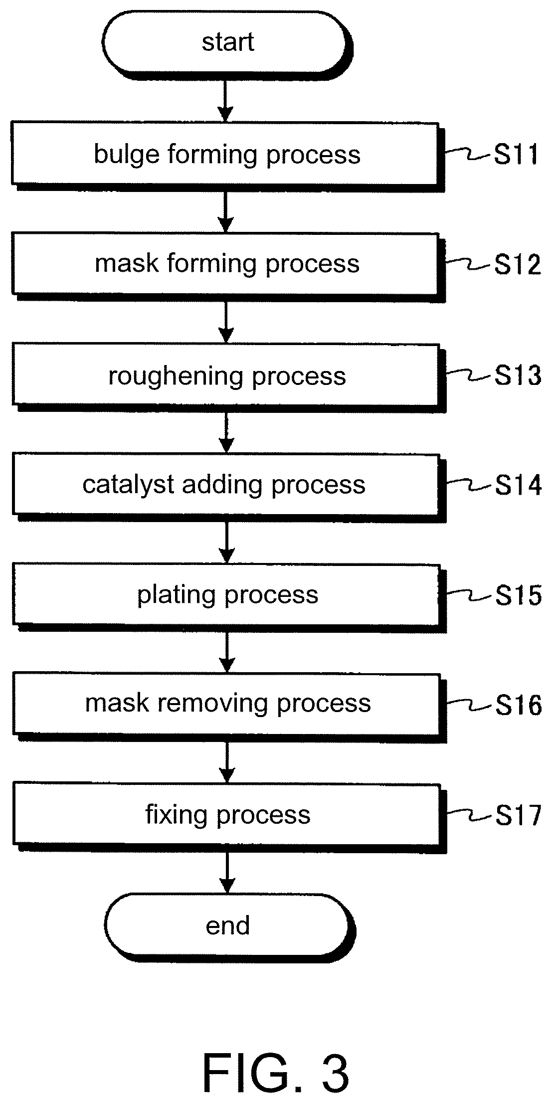
[0045]Now, with reference to FIGS. 3 and 4, a plating method according to a second embodiment will be described. However, in the second embodiment, in order to avoid a repeated description, parts different from those of the first embodiment will be described, and parts having the same configurations as those of the first embodiment will be denoted by the same reference symbols, and will be described. FIG. 3 is a flow chart illustrating the plating method according to the second embodiment. FIG. 4 is an explanatory view illustrating the plating method according to the second embodiment.

[0046]The plating method of the second embodiment forms a bulge 16 and a plating mask 17 on an object 1 by inkjet printing, and plates the object 1 having the bulge 16 and the plating mask 17 formed thereon, and then removes the plating mask 17.

[0047]As shown in FIG. 3, the plating method of the second embodiment sequentially performs a bulge forming process S11, a mask forming process S12, a roughenin...

third embodiment

[0067]Now, a plating method according to a third embodiment will be described. However, in the third embodiment, in order to avoid a repeated description, parts different from those of the first embodiment will be described, and parts having the same configurations as those of the first embodiment will be denoted by the same reference symbols, and will be described. FIG. 5 is a flow chart illustrating the plating method according to the third embodiment.

[0068]As shown in FIG. 5, the plating method of the third embodiment sequentially performs a bulge forming process S21, a heating process S22, a roughening process S23, a catalyst adding process S24, a plating process S25, and a fixing process S26. However, the plating method needs only to perform at least the bulge forming process S21, the heating process S22, and the plating process S25, and thus each of the other processes may be appropriately omitted.

[0069]The bulge forming process S21 is a process of forming a bulge 16 on an obj...


PUM

PropertyMeasurementUnit
viscosityaaaaaaaaaa
viscosityaaaaaaaaaa
heat resistant temperatureaaaaaaaaaa

Abstract

The present invention provides a plating method capable of easily performing various decorative plating processes. The plating method includes a bulge forming process of forming a bulge on an object to be plated by ejecting ink drops of first UV-curable ink from an inkjet head such that the ejected ink drops land on the object, and a plating process of plating the object having the bulge formed thereon, after the bulge forming process. Also, in the bulge forming process, the bulge is formed such that a second surface of the bulge to be plated has surface roughness different from that of a first surface of the object to be plated.

Description

CROSS-REFERENCE TO RELATED APPLICATIONS[0001]This application claims the priority benefit of Japanese application serial no. 2016-106601, filed on May 27, 2016 and Japanese application serial no. 2017-051764, filed on Mar. 16, 2017. The entirety of each of the above-mentioned patent application is hereby incorporated by reference herein and made a part of this specification.BACKGROUND OF THE INVENTION1. Technical Field[0002]The present invention relates to a plating method of performing a plating process on objects.2. Related Art[0003]In the related art, as plating methods of performing plating processes on objects, methods of depositing metal layers on substrates by forming photoresist patterns on the substrates using photomasks and performing electroless plating processes using the formed photoresist patterns as photomasks are known (see Japanese Patent Application Laid-Open No. 2007-57749 for instance).[0004]According to those methods such as the plating method disclosed in JP-A-...

Claims


Application Information

Patent Timeline
Patent Type & Authority Patents(United States)
IPC IPC(8): C09D11/101
CPCC09D11/101C23C18/1605C23C18/1608C23C18/1653C23C18/1662C23C18/1692C23C18/1806C23C18/1831C23C18/1844C23C18/1855C23C18/1879C23C18/1893C23C18/2013C23C18/2086C23C18/22C23C18/285C23C18/30C25D5/02C25D5/022
Inventor OHNISHI, MASARUITO, TOSHIYA
Owner MIMAKI ENG
Learn More