Limiting dispersion of IR radiation from a heater element during plastic welding

a technology of limiting ir radiation and heater element, which is applied in the direction of distortion, discoloration, and other parts, which can solve the problems of plastic parts being other parts may be affected in undesired ways, so as to increase the operating efficiency of heating tools.

Active Publication Date: 2020-02-04
SPM AUTOMATION CANADA
View PDF4 Cites 7 Cited by
  • Summary
  • Abstract
  • Description
  • Claims
  • Application Information

AI Technical Summary

Benefits of technology

[0009]This disclosure relates to heating tools for melting plastic of plastic parts by either contact welding or non-contact welding, characterized by mitigation of dispersion of IR radiation beyond an intended location at which a weld joint is to be created, and to a related method for mitigating dispersion of IR radiation beyond an intended location for a weld joint. Operating efficiency of a heating tool may be increased by recovery of dispersed IR radiation.
[0010]A plastic welding heating tool comprises a heater, and / or a heater element heated by a heater, for melting plastic of a plastic part where a weld joint is to be created. An IR radiation shield is mounted on the heating tool and is shaped to selectively shield surfaces of the heating tool and / or of the plastic part from receiving incident IR radiation. The shield confronts one or more unshielded zones of the tool and / or plastic part, leaving one or more other zones unshielded. IR radiation is directly incident on an unshielded zone. The shield, by confronting one or more unshielded zones of the tool and / or plastic part, redirects incident IR radiation by reflecting a significant percentage of IR radiation which would otherwise be incident on any such unshielded zone. The direction of reflection is a function of the angle of incidence of IR on any particular area of the shield surface. IR radiation may be reflected fully or partially back toward its point of origin, allowing energy of the reflected radiation to be recovered by the heating tool. The energy recovery is additive to the thermal energy which is being added by the heater so that the sum of the energies maintains desired temperature of the heating tool for melting plastic. That capability enables the quantity of thermal energy being added by a heater to be significantly reduced from what it would be in the absence of the shield. The result is a more energy-efficient method for both non-contact welding and contact welding of a plastic part.
[0011]If IR radiation is directly incident on portions of the surface of a plastic part beyond a surface portion where a weld joint is intended to be created, the plastic part may be affected in undesired ways, such as distortion, discoloration, etc. If the plastic part in which the weld joint is being created is one part of a multi-part assembly, dispersed IR radiation may be incident on other parts of the assembly, both plastic and non-plastic, and those other parts may be affected in undesired ways. Use of an IR shield can avoid such undesired consequences.
[0014]A material having emissivity no greater than 0.3 is preferred for plastic welding applications. For non-contact plastic welding, aluminized steel (steel which has an aluminum-silicon alloy coating) provides an efficient and cost-effective shield. It can be easily shaped to simple- and / or complex-shaped heating tool geometries, it can withstand high temperatures required for non-contact plastic welding, and it has good corrosion resistance. Furthermore, it has emissivity significantly less than 0.3.

Problems solved by technology

If IR radiation is directly incident on portions of the surface of a plastic part beyond a surface portion where a weld joint is intended to be created, the plastic part may be affected in undesired ways, such as distortion, discoloration, etc.
If the plastic part in which the weld joint is being created is one part of a multi-part assembly, dispersed IR radiation may be incident on other parts of the assembly, both plastic and non-plastic, and those other parts may be affected in undesired ways.

Method used


Image

  • Limiting dispersion of IR radiation from a heater element during plastic welding
  • Limiting dispersion of IR radiation from a heater element during plastic welding
  • Limiting dispersion of IR radiation from a heater element during plastic welding

Examples


Embodiment Construction

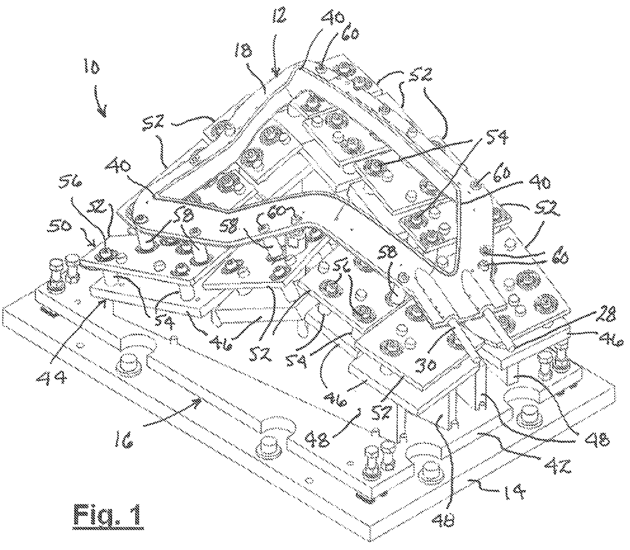
[0024]FIG. 1 shows a heating tool 10 for performing an operation on a plastic part (not shown) to melt plastic at a location where a weld joint is to be created. Tool 10 comprises, as its heater element, a hot plate assembly 12 which is supported on a tooling plate 14 by a support structure 16.

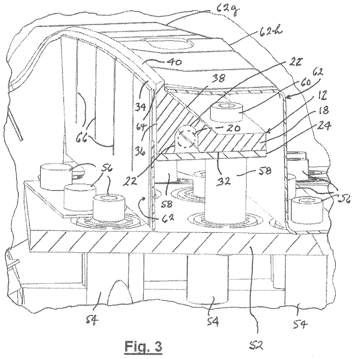
[0025]Hot plate assembly 12 comprises a hot plate which has a thermally conductive body 18 whose shape has a feature which corresponds to that of a surface of a plastic part at a location where a weld joint is to be created. FIGS. 3 and 4 show hot plate assembly 12 to further comprise an electric heater 20 (shown in phantom) which is disposed within a channel 22 in body 18 and captured within channel 22 by a retainer plate 24 fastened to body 18. An example of heater 20 is a conventional flex heater pressed against body 18 by fastening of retainer plate 24 to body 18. FIG. 1 shows electrical leads 28, 30 of heater 20 extend outward from body 18 for connection to an electric power source (not s...


PUM

PropertyMeasurementUnit
emissivityaaaaaaaaaa

Abstract

In a process for welding plastic parts together, an IR shield redirects IR radiation emitted from a heater of a heating tool so that IR radiation which would otherwise be directly incident on certain portions of a plastic part and / or on other parts of the heating tool is avoided.

Description

REFERENCE TO RELATED APPLICATION AND PRIORITY CLAIM[0001]This application claims the priority of Provisional Patent Application No. 62 / 366,178, filed 25 Jul. 2016, the entire content of which is incorporated herein by reference.TECHNICAL FIELD[0002]This disclosure relates to welding of plastic parts.BACKGROUND[0003]Plastic parts are commonly manufactured by a molding process, such as blow molding or injection molding, and then further processed by one or more operations such as boring, drilling, and / or welding.[0004]Welding is a process for joining plastic parts together by melting plastic at a location in each part where a weld joint is to be created, then placing the parts together so that their melt pools merge together, and then allowing the melt pools to solidify and create the finished weld joint.[0005]One type of plastic welding known as contact welding is performed by a heating tool which has a heater element, a hot plate for example, which is heated by a heat source. Therma...

Claims


Application Information

Patent Timeline
Patent Type & Authority Patents(United States)
IPC IPC(8): B29C65/30B29C65/14
CPCB29C65/1412B29C65/30B29C65/1432B29C65/1487B29C65/1496B29C65/20B29C65/305B29C66/003B29C66/242B29C66/244B29C66/301B29C66/348B29C66/54B29C66/73921B29C66/8167B29C66/81831
Inventor PUPOVAC, RADETOUESNARD, ZACHARYHOLTKAMP, CHRISTIAN PETERNOVAKOVIC, BORIS
Owner SPM AUTOMATION CANADA
Why Eureka
Try Eureka