Tank piston with improved seal and cover

a tank piston and seal technology, applied in the field of tank pistons, can solve the problems of reducing the service life of the seal, affecting the sealing performance of the seal, so as to prolong the seal's life and facilitate the movement within the tank. the effect of sealing and sealing sealing

Active Publication Date: 2020-02-18
PISTON TANK CORP
View PDF34 Cites 5 Cited by
  • Summary
  • Abstract
  • Description
  • Claims
  • Application Information

AI Technical Summary

Benefits of technology

[0010]Embodiments of the present invention comprise a tank piston with an improved seal having a cap, a cylindrical body connected to the periphery of the cap, a circumferential channel adjacent to the periphery of the cap, and an annular seal held within the channel by an annular sheet or other cover. In one aspect of the invention, the annular sheet secures the seal within the channel and is attached to the piston by a pair of rings positioned on opposite sides of the channel and attached to the lands adjacent to the top of the channel. In another aspect of the invention, the annular sheet is made from a friction reducing material that is sandwiched between the rings and the channel lands and enables the piston to more easily move within the tank and subsequently extend the lifespan of the seal. Another aspect of the present invention is the annular sheet attached to the piston at lands that are relatively closer to the interior wall of the tank than the base of the channel. In another aspect of the invention, the empty space between the front of the sheet and the front of the seal is minimized as compared with the prior art.

Problems solved by technology

Given this continuity in the contact, the soft, pliable material of the seal is subject to friction, abrasion, and wear as it slides against the hard, rigid material of the tank which could damage the seal or cause the seal to become dislodged from the circumferential channel.
However, the formation of the channel in the '054 Patent using angle rings is problematic because it leaves a large empty space between the sheath and the seal within the angle ring.
As the piston moves through the tank, the material being pushed up against the front side of the sheath would force the sheath inward into the empty space, and the sheath could contact the front edge of the angle ring that forms the channel sidewall which could cause the sheath to tear or otherwise be damaged, thereby producing more friction and potentially allowing the seal to come loose from its position within the channel.
Regardless of how tight the sheath is placed over a compression-type cell foam seal, the sheath must necessarily lose some of its tautness when the piston is within the tank, resulting in some slack in the sheath.
Therefore, according to the design of the channels in the '054 Patent, if a non-pneumatic compression-type of seal is used, the seal would be compressed between the channel and the tank's inner wall, necessarily resulting in some slack in the sheath which would more likely cause the sheath to contact the angle ring that forms the channel's front wall, resulting in the failure of the sheath.
Therefore, while the seal assembly in the '054 Patent (including the sheath, seal, and the channel design) may have some success with pneumatic seals as contemplated in the '054 Patent but would be unsatisfactory for use with cell foam seals or any other type of compression-type seal.

Method used


Image

  • Tank piston with improved seal and cover
  • Tank piston with improved seal and cover
  • Tank piston with improved seal and cover

Examples


Embodiment Construction

[0022]The following description of the preferred embodiment(s) is merely exemplary in nature and is in no way intended to limit the invention, its application, or uses.

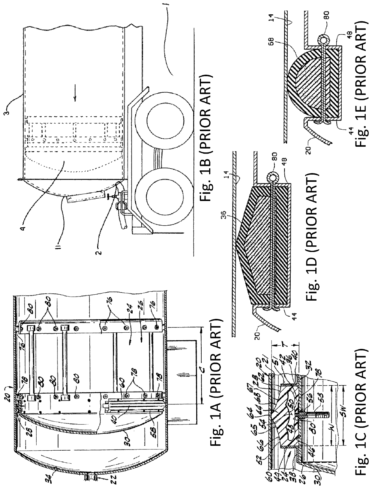
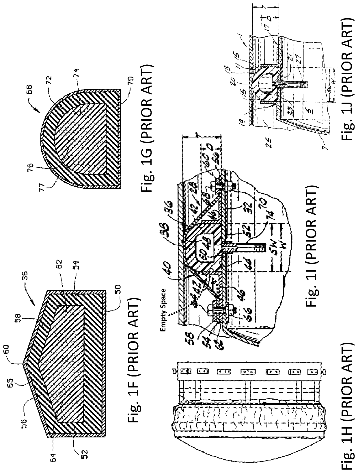
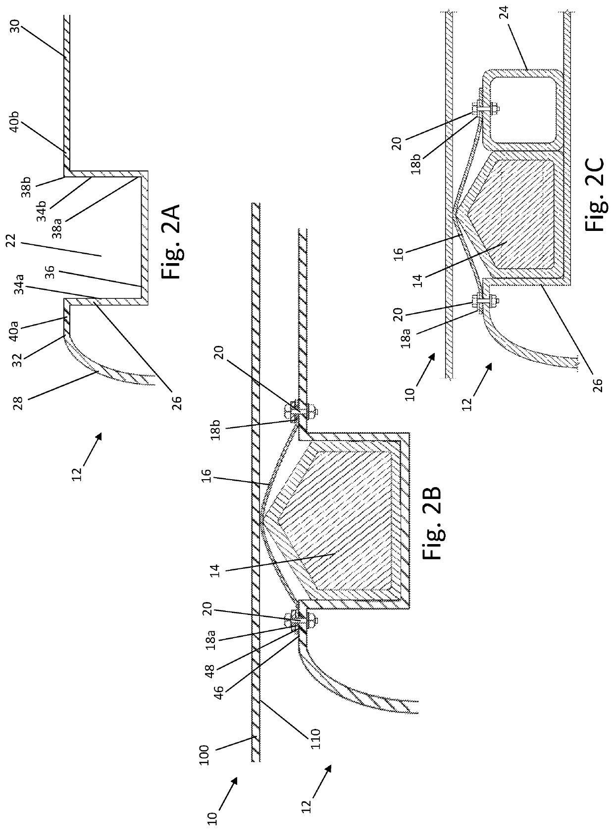
[0023]Generally, as shown in FIGS. 2-6 and 8, the present invention is a sealed piston 10 having a piston 12 with a cap 28 and a cylindrical body 30. The cylindrical body has a circumferential channel 22 with an annular seal 14 having a bottom portion 60a held within the channel by at least a partial friction fit and an upper portion 60b radially extending from the bottom portion and protruding out of the channel. An annular sheet 16 covers the entire upper portion of the annular seal, and opposite ends of the sheet are sandwiched between rings 18 and lands 40 on opposite sides of the channel. The rings are secured to the lands to keep the sheet taught over the upper portion of the seal to further secure the seal within the channel. Additionally, the piston body has alignment pads 104 that contact the interior wall 11...


PUM


Abstract

The present invention relates to a tank piston with an improved seal having a cap, a body attached to the periphery of the cap, a circumferential channel adjacent to the periphery of the cap and an annular seal held within the channel by an annular sheet. In one aspect of the invention the annular sheet secures the seal within the channel and is attached to the piston by a ring proximate to the periphery of the cap and a ring proximate to the back side of the circumferential channel. In another aspect of the invention the annular sheet is made from a friction reducing material and enables the piston to more easily move within the tank and subsequently extends the lifespan of the seal. Additionally, the annular sheet is fitted to the seal and attached above the front sidewall of the channel.

Description

CROSS-REFERENCE TO RELATED APPLICATIONS[0001]This application claims priority from U.S. Provisional Patent Application Ser. No. 62 / 479,806 filed on Mar. 31, 2017 which is hereby incorporated by reference.STATEMENT REGARDING FEDERALLY SPONSORED RESEARCH[0002]Not Applicable.APPENDIX[0003]Not Applicable.BACKGROUND OF THE INVENTIONField of the Invention[0004]The present invention relates to a piston disposed within a tank that is used to store and / or transport semisolid materials and viscous liquids, and more particularly relates to an improved seal between the interior of the tank and the piston.Related Art[0005]Tanks used for storing and transporting semisolid materials, such as grease, silicone, and ground or comminuted food products like peanut butter, and viscous liquids, such as oil, grease, and printing ink, typically have a reciprocating piston for pushing the material out of the tank. These tanks are usually cylindrical and have at least one outlet at one end through which the ...

Claims


Application Information

Patent Timeline
Patent Type & Authority Patents(United States)
IPC IPC(8): F16J9/10F15B15/10F16J9/12F16J15/46
CPCF15B15/10F16J9/12F16J9/10F16J15/46B60P3/221B65D88/60
Inventor DEJOHN, ANTHONY FRANKDUNCAN, CHRISTOPHER KEITH
Owner PISTON TANK CORP
Why Eureka
Try Eureka