Fast projection matching method for computed tomography images

a computed tomography and projection matching technology, applied in image enhancement, instruments, applications, etc., can solve the problems of unexpected image drift, inability to achieve precise positioning accuracy, and complex and time-consuming conventional mechanical alignment procedures

Active Publication Date: 2020-02-18
NAT SYNCHROTRON RADIATION RES CENT
View PDF22 Cites 0 Cited by
  • Summary
  • Abstract
  • Description
  • Claims
  • Application Information

AI Technical Summary

Problems solved by technology

Along with the improvement of the spatial resolution in image technologies, the accuracy of the sample carrier cannot achieve the requirement of precise positioning when the resolution requires nano-level accuracy.
Although the minor mechanical differences at each rotation angle of the sample carrier is correctable by sensitive and accurate sensing and feedback systems, conventional mechanical alignment procedures are still complex and time-consuming.
Besides, unexpected image drifting could occur due to the heat effects on the sample or system generated by the illumination of detecting lights while capturing images.
Such integrated image positioning difference is not resolvable by mechanical alignments.
However, hand alignments consume work force and time, and the additional positional markers do not always appear at the expected positions may cause troubles when selecting the observing area of the target object in interest.
However, some algorithms do not consider and correct the mechanism for the actual movements of the object during rotations, and some of which do not apply accurate methods for correcting the rotation offsets of the object.
Some other algorithms are too complex.
These conventional algorithms have a major problem of massive statistics and computations, which greatly increase the hardware specification of computing requirements and limit the efficiency of processing CT data.

Method used


Image

  • Fast projection matching method for computed tomography images
  • Fast projection matching method for computed tomography images
  • Fast projection matching method for computed tomography images

Examples


Embodiment Construction

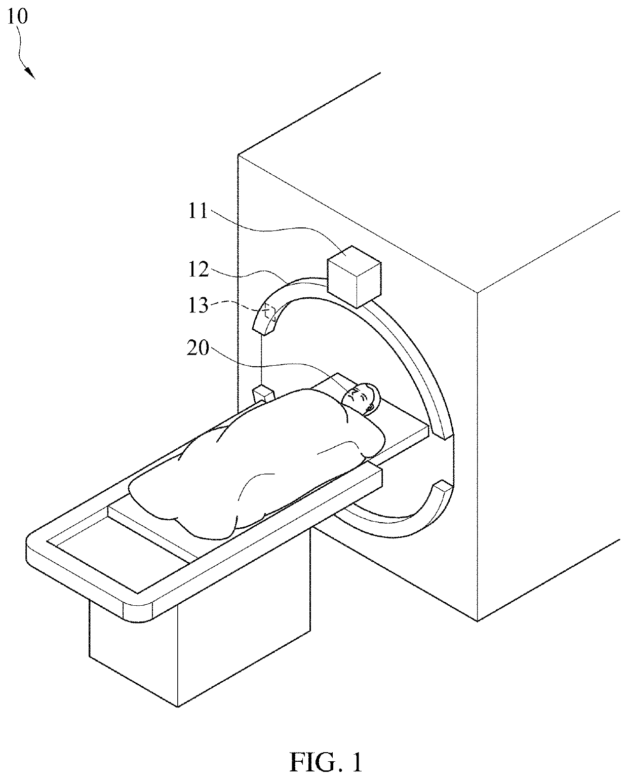
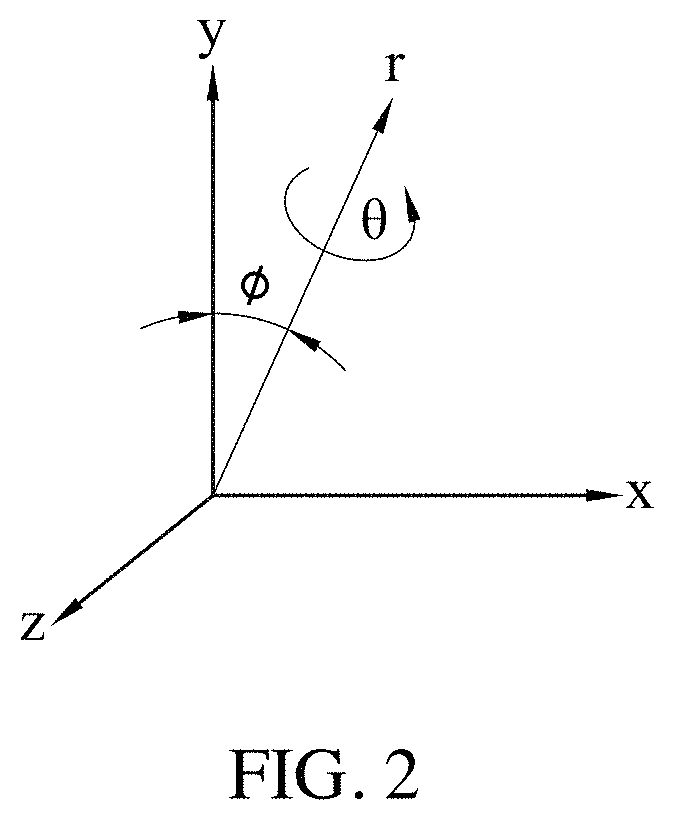
[0035]FIG. 1 illustrates an explanatory perspective view of a computed tomography apparatus 1 adapted for a fast projection matching method for computed tomography images according to an embodiment of the instant disclosure. FIG. 2 illustrates an explanatory perspective view of a reference coordinate system. Referring to FIG. 1 and FIG. 2 jointly, the computed tomography apparatus 1 includes a light emitting unit 11, a data-receiving unit 12 and a processing unit 13. The processing unit 13 is coupled with the data-receiving unit 12. In an embodiment, the processing unit 13 may be installed in the data-receiving unit 12.

[0036]During the computed tomography process, the light emitting unit 11 and the data-receiving unit 12 and the object 20 may rotate corresponding to each other. For example, the object 20 is still, while the light emitting unit 11 and the data-receiving unit 12 rotate corresponding to the object 20; alternatively the light emitting unit 11 and the data-receiving unit...


PUM

PropertyMeasurementUnit
angleaaaaaaaaaa
angleaaaaaaaaaa
angleaaaaaaaaaa

Abstract

A fast projection matching method for computed tomography (CT) images is provided. The method mainly bases on an iterative algorithm. The algorithm simplifies a traditional issue of three-dimensional projection matching into a two-dimensional projection-matching problem by pre-correcting the Y-axis offset and ϕ shift of each projection intensity image using common-line concept, thereby making the complex CT alignment processing faster and more reliable. This majorly reduces the hardware requirements for CT and data processing, which facilitates the applications in other three dimensional tomographic techniques, such as X-ray micro-CT or electron tomography.

Description

CROSS-REFERENCE TO RELATED APPLICATION[0001]This non-provisional application claims priority under 35 U.S.C. § 119(a) to Patent Application No. 106140007 filed in Taiwan, R.O.C. on Nov. 17, 2017, the entire contents of which are hereby incorporated by reference.BACKGROUNDRelated Field[0002]The instant disclosure relates to a fast projection matching method for computed tomography images.Related Art[0003]Three-dimensional (3D) computed tomography (CT) has broad applications in the fields of medical and material structural measurements. Currently, the way to reconstruct 3D images with CT technology is to obtain by capturing sample projection images in different directions and conducting a 3D image-reconstruction algorithm. However, the accuracy of 3D image-reconstruction significantly relates to the spatial positioning accuracy of these projection images. Along with the improvement of the spatial resolution in image technologies, the accuracy of the sample carrier cannot achieve the r...

Claims


Application Information

Patent Timeline
Patent Type & Authority Patents(United States)
IPC IPC(8): G06T11/00G06T7/00A61B6/00G01N23/046A61B6/03
CPCG06T7/0012G06T11/003G06T11/008G01N23/046G06T2207/10081A61B6/032A61B6/5235
Inventor WANG, CHUN-CHIEH
Owner NAT SYNCHROTRON RADIATION RES CENT
Why Eureka
Try Eureka