Supercharge Your Innovation With Domain-Expert AI Agents!

Focus ring and plasma processing apparatus

a plasma processing and focus ring technology, applied in the direction of electrical apparatus, basic electric elements, electric discharge tubes, etc., can solve the problems of increasing the temperature of the focus ring, increasing the etching rate, and poor thermal conductivity between the focus ring and the top surface of the outer peripheral portion of the mounting table, and achieve the effect of sufficient thermal conductivity

Active Publication Date: 2020-02-18
TOKYO ELECTRON LTD
View PDF11 Cites 0 Cited by
  • Summary
  • Abstract
  • Description
  • Claims
  • Application Information

AI Technical Summary

Benefits of technology

This configuration ensures sufficient thermal conductivity and adhesivity, allowing for consistent heat transfer and preventing detachment issues, thus improving etching uniformity and extending the focus ring's lifespan without the need for mechanical pressing units.

Problems solved by technology

In the above configuration, it is general that a vacuum insulating layer is formed between the focus ring and a top surface of the outer peripheral portion of the mounting table in the depressurized processing chamber and, thus, thermal conductivity between the focus ring and the top surface of the outer peripheral portion of the mounting table becomes considerably poor.
When the vacuum insulating layer is formed, it is difficult to cool the focus ring, so that the temperature of the focus ring is increased.
As a result, an etching rate and a hole forming property (in which a hole can be reliably formed to a predetermined depth by etching) of the outer peripheral portion of the semiconductor wafer which is close to the focus ring become poorer, and an etching aspect ratio become smaller.
In other words, the etching characteristics of the outer peripheral portion of the semiconductor wafer become poorer.
Accordingly, it is difficult to perform uniform etching on a plurality of semiconductor wafers in a same lot.
In the case of attaching the thermally conductive sheet, existence of even an extremely small amount of air between the focus ring and the thermally conductive sheet or between the thermally conductive sheet and the portion above the outer peripheral portion of the mounting table leads to insufficient thermal conductivity and insufficient cooling of the focus ring.
As the focus ring is consumed, the in-plane uniformity in the processing of the semiconductor wafer becomes poorer.
However, when the consumed focus ring is detached for exchange from the top surface of the outer peripheral portion of the mounting table, the thermally conductive sheet firmly adhered by the mechanical pressing unit may be broken.

Method used


Image

  • Focus ring and plasma processing apparatus
  • Focus ring and plasma processing apparatus
  • Focus ring and plasma processing apparatus

Examples


Embodiment Construction

[0019]The present invention relates to a plasma processing apparatus and a thermally conductive sheet for facilitating thermal conduction which is used for the plasma processing apparatus. First, the plasma processing apparatus used for implementing the present invention will be described.

[0020](Configuration of the Present Embodiment)

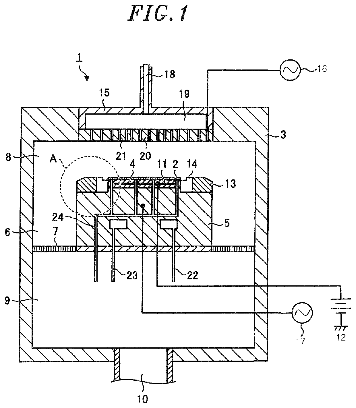
[0021]FIG. 1 is a schematic cross sectional view showing an example of a plasma processing apparatus used for implementing the present invention. The plasma processing apparatus 1 includes a chamber 3 accommodating a semiconductor wafer 2. As a mounting table for mounting thereon a semiconductor wafer 2, an electrostatic chuck 4 and a cylindrical susceptor 5 are provided in the chamber 3. A side exhaust passageway 6 through which a gas is discharged is formed between an inner wall surface of the chamber 3 and a side surface of the susceptor 5. A gas exhaust plate 7 that is a porous plate is provided in the side exhaust passageway 6. The gas exhaust pla...


PUM

PropertyMeasurementUnit
Shore hardnessaaaaaaaaaa
viscosityaaaaaaaaaa
lengthaaaaaaaaaa

Abstract

A focus ring to be detachably attached to a top surface of an outer peripheral portion of a mounting table in a processing chamber, includes: an annular main body having a back surface to be attached to the top surface of the outer peripheral portion of the mounting table. And a thermally conductive sheet fixed to the annular main body, the thermally conductive sheet being interposed between the annular main body and the top surface of the outer peripheral portion of the mounting. The thermally conductive sheet is fixed as one unit to the annular main body by coating an unvulcanized rubber on one surface of the thermally conductive sheet, bringing said one surface into contact with the annular main body, and heating the thermally conductive sheet and the annular main body to vulcanize and to adhere the thermally conductive sheet to the annular main body.

Description

CROSS-REFERENCE TO RELATED APPLICATIONS[0001]This application is a Divisional of U.S. patent application Ser. No. 14 / 524,049, filed Oct. 27, 2014, and claims priority from Japanese Patent Application No. 2013-222563, filed Oct. 25, 2013, with the Japan Patent Office. The benefit of priority is claimed to each of the foregoing, and the entire contents of each of the foregoing are incorporated herein by reference.FIELD OF THE INVENTION[0002]Various aspect and embodiments of the present invention relate to a focus ring and a plasma processing apparatus.BACKGROUND OF THE INVENTION[0003]In a plasma processing apparatus used in a semiconductor device manufacturing process, a substrate to be processed such as a semiconductor wafer or the like is mounted on a substrate mounting table provided in a processing chamber, and a high frequency voltage is applied to the processing chamber under a vacuum environment. Accordingly, a plasma is generated in the processing chamber, and, e.g., etching o...

Claims


Application Information

Patent Timeline
Patent Type & Authority Patents(United States)
IPC IPC(8): C08L27/16H01J37/32
CPCH01J37/32091H01J37/32642C08L27/16
Inventor NAGAYAMA, NOBUYUKISATOH, NAOYUKIOKA, MASAHIKOMATSUOKA, YASUYUKI
Owner TOKYO ELECTRON LTD
Features
  • R&D
  • Intellectual Property
  • Life Sciences
  • Materials
  • Tech Scout
  • Unparalleled Data Quality
  • Higher Quality Content
  • 60% Fewer Hallucinations
Learn More