Unlock instant, AI-driven research and patent intelligence for your innovation.

Fuel injection control device

a control device and fuel injection technology, applied in electrical control, mechanical equipment, machines/engines, etc., can solve the problem that the amount of fuel injection in partial lift injection cannot be controlled with a high degree of accuracy, and achieve the effect of high correlation and high degree of accuracy

Active Publication Date: 2020-03-03
TOYOTA JIDOSHA KK
View PDF14 Cites 2 Cited by
  • Summary
  • Abstract
  • Description
  • Claims
  • Application Information

AI Technical Summary

Benefits of technology

The solution enables precise control of fuel injection quantity in partial lift injection by accounting for temperature-induced changes in electromagnetic coil characteristics, improving accuracy and robustness against variations in injection characteristics across different machine types.

Problems solved by technology

In the partial lift injection, since a conduction time is extremely short, a period of time when valve opening operation cannot start and a fuel is not injected (namely invalid injection period) because an electromagnetic force is small in spite of the fact that the period is immediately after the start of the conduction and during the conduction accounts for a large proportion of the conduction time.
As a result, an invalid injection period varies, correspondence between a requested injection quantity and a conduction time (namely injection characteristic) varies undesirably, and a fuel injection quantity in partial lift injection cannot be controlled with a high degree of accuracy.

Method used


Image

  • Fuel injection control device
  • Fuel injection control device
  • Fuel injection control device

Examples


first embodiment

[0022](First Embodiment)

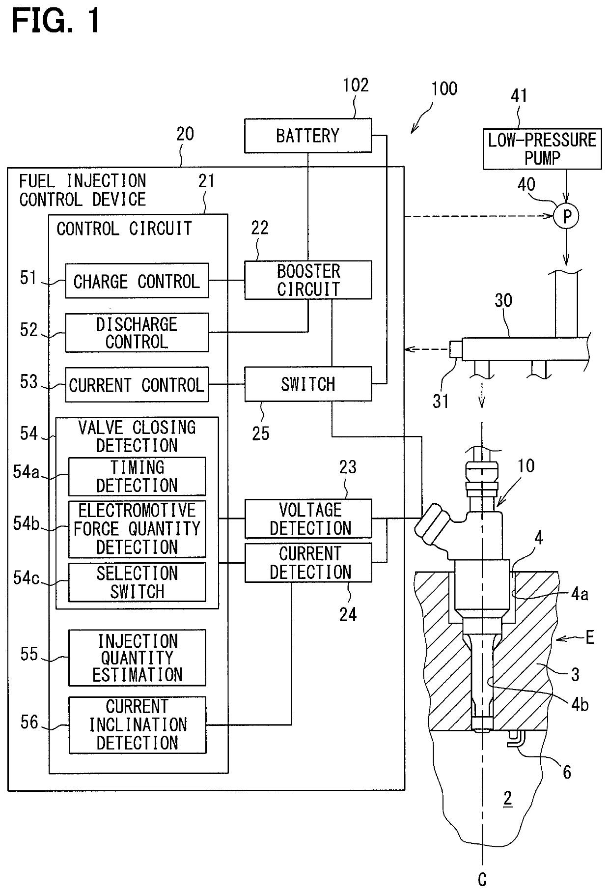
[0023]A first embodiment according to the present disclosure is explained in reference to FIGS. 1 to 10. A fuel injection system 100 shown in FIG. 1 includes a plurality of fuel injection valves 10 and a fuel injection control device 20. The fuel injection control device 20 controls the opening and closing of the fuel injection valves 10 and controls fuel injection into a combustion chamber 2 of an internal combustion engine E. The fuel injection valves 10: are installed in an internal combustion engine E of an ignition type, for example a gasoline engine; and inject a fuel directly into a plurality of combustion chambers 2 of the internal combustion engine E respectively. A mounting hole 4 penetrating concentrically with an axis C of a cylinder is formed in a cylinder head 3 constituting the combustion chamber 2. A fuel injection valve 10 is inserted into and fixed to the mounting hole 4 so that the tip may be exposed into the combustion chamber 2.

[0024]A fu...


PUM


Abstract

A fuel injection control device has a detection unit, a correction value calculation unit, and a conduction time calculation unit. The detection unit detects a current increase speed that is a speed of increasing an electric current flowing in an electromagnetic coil in accordance with the start of conducting the electromagnetic coil during partial lift injection in which a valve body starts valve closing operation before the valve body reaches a maximum valve opening position after the valve body starts valve opening operation. The correction value calculation unit calculates a correction value for a requested injection quantity on the basis of the detected current increase speed. The conduction time calculation unit calculates a conduction time of the electromagnetic coil during the partial lift injection on the basis of the requested injection quantity corrected by the correction value.

Description

CROSS REFERENCE TO RELATED APPLICATION[0001]This application is based on Japanese Patent Application No. 2016-93320 filed on May 6, 2016, the disclosure of which is incorporated herein by reference.TECHNICAL FIELD[0002]The present disclosure relates to a fuel injection control device to control an injection quantity of a fuel injected through a fuel injection valve.BACKGROUND ART[0003]In Patent Literature 1, a fuel injection valve to inject a fuel by operating a valve body for valve opening by an electromagnetic force caused by conduction of an electromagnetic coil is disclosed. Further, a fuel injection control device to control a valve opening time of a valve body by controlling a time for energizing the electromagnetic coil and thus control an injection quantity injected per one time valve opening of the valve body is disclosed. A conduction time is set at a time corresponding to an injection quantity that is requested (requested injection quantity).PRIOR ART LITERATURESPatent Li...

Claims


Application Information

Patent Timeline
Patent Type & Authority Patents(United States)
IPC IPC(8): F02D41/34F02D41/24F02D41/20F02D41/30F02M51/06F02D41/38
CPCF02D41/3094F02D41/345F02M51/061F02D41/247F02D41/20F02D2041/2055F02D2041/389F02D2200/0614Y02T10/44F02D2041/2058Y02T10/40
Inventor SATAKE, NOBUYUKINAKANO, TOMOHIRO
Owner TOYOTA JIDOSHA KK