
Piezoelectric driving device, motor, robot, and pump

a driving device and piezoelectric technology, applied in the direction of machines/engines, manufacturing tools, positive displacement liquid engines, etc., can solve the problems of less easily occurring piezoelectric layer cracks, less easily occurring dielectric breakdown at the end portion of the wiring layer, and sometimes caused piezoelectric layer cracks, etc., to achieve high reliability

Active Publication Date: 2020-03-03
SEIKO EPSON CORP
View PDF21 Cites 0 Cited by
  • Summary
  • Abstract
  • Description
  • Claims
  • Application Information

AI Technical Summary

Benefits of technology

This patent aims to provide a piezoelectric driving device with a thin-film piezoelectric element that has good electroconductivity and insulation resistance. Additionally, this patent also provides an ultrasonic motor, a robot, and a pump that utilize the piezoelectric driving device. The technical effects of this patent include high reliability and performance of the piezoelectric driving device in various applications such as ultrasonic motors, robots, and pumps.

Problems solved by technology

However, since a piezoelectric layer of the thin-film piezoelectric element is a thin film, a crack is sometimes caused in the piezoelectric layer by stress generated when the driving is performed.
Therefore, dielectric breakdown at the end portions of the wiring layer less easily occurs.
Therefore, dielectric breakdown at the end portion of the wiring layer less easily occurs and insulation resistance is satisfactory.

Method used


Image

  • Piezoelectric driving device, motor, robot, and pump
  • Piezoelectric driving device, motor, robot, and pump
  • Piezoelectric driving device, motor, robot, and pump

Examples


experiment examples

[0115]7. Experiment Examples

[0116]The invention is further explained below with reference to experiment examples. However, the invention is not limited to the experiment examples.

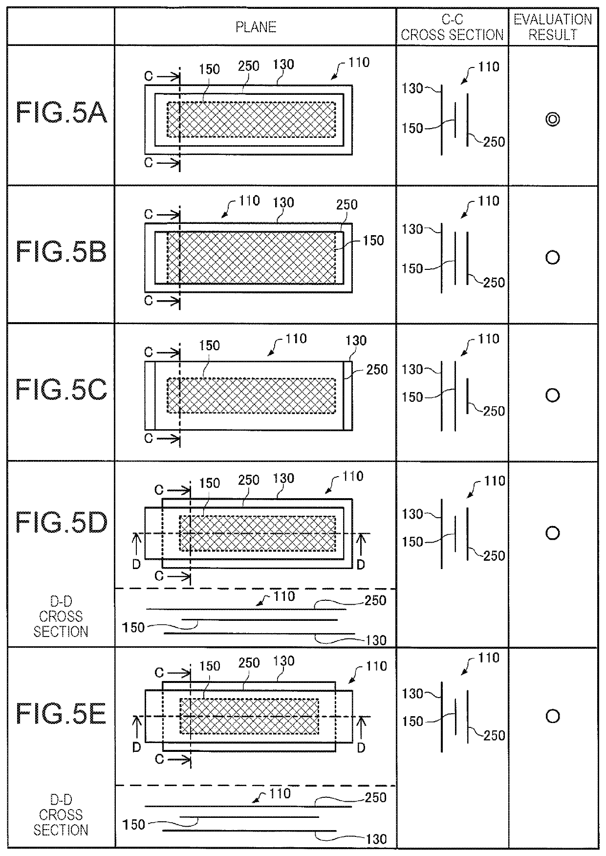
[0117]Forty samples equivalent to the piezoelectric elements 110 according to the invention (samples satisfying the conditions of the disposition of the first electrode layer 130, the second electrode layer 150, and the wiring layer 250) and forty samples not satisfying the conditions of the piezoelectric elements of the invention were created. In both the samples, on a silicon substrate, Pt was used as a first electrode layer, PZT was used as a piezoelectric layer, Pt was used as a second electrode layer, Al2O3 was used as an insulating layer, and Cu was used as a wiring layer. The second electrode layer and the wiring layer were conducted by a contact section.

[0118]In the experiment examples, samples satisfying the conditions of the disposition of the first electrode layer 130, the second electrode layer ...


PUM


Abstract

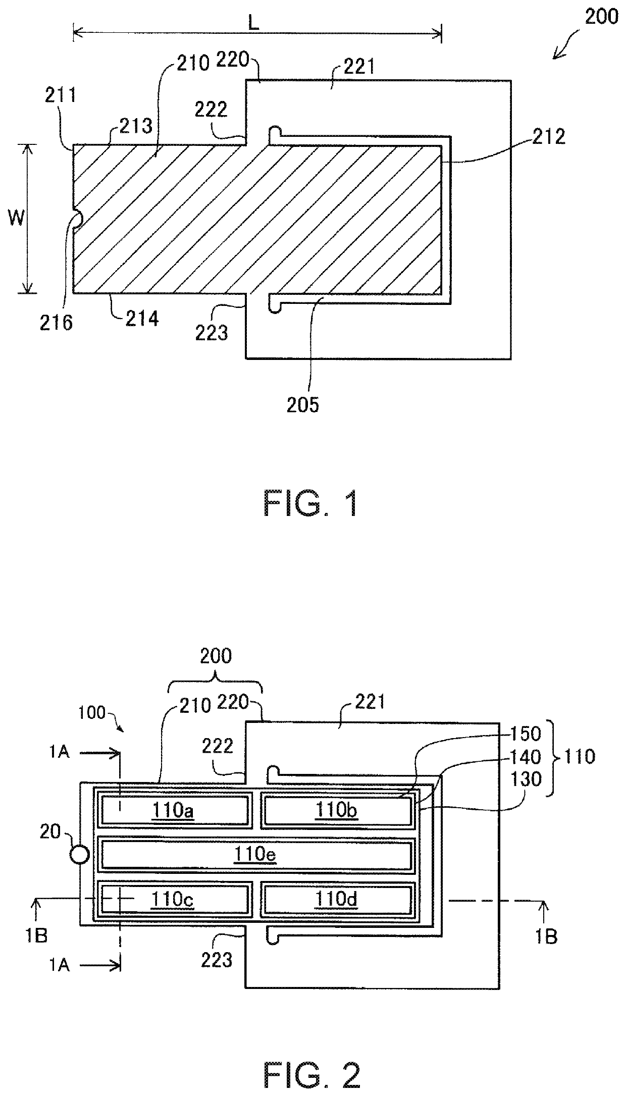
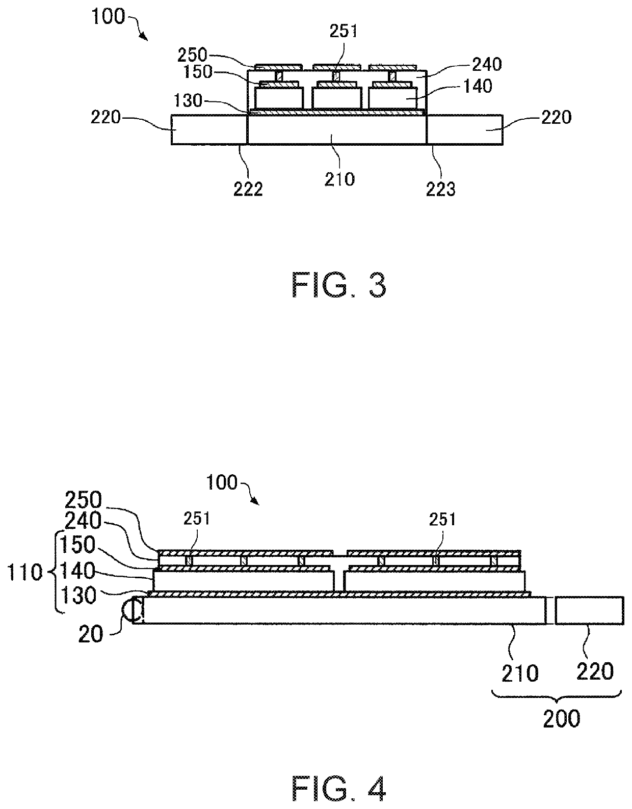
A piezoelectric driving device includes a vibrating plate, a first electrode, a piezoelectric layer, a second electrode layer provided above the vibrating plate. An active section is formed in a portion where the first electrode layer, the piezoelectric layer, and the second electrode layer overlap one another. The active section has a longitudinal direction and a latitudinal direction in plan view. At both ends in the latitudinal direction, ends of the first electrode layer are disposed in the same positions as ends of the wiring layer or further on the outer side than the ends, ends of the second electrode layer are disposed in the same positions as the ends of the wiring layer or further on the inner side than the ends, and the ends of the first electrode layer are disposed further on the outer side than the ends of the second electrode layer.

Description

BACKGROUND[0001]1. Technical Field[0002]The present invention relates to a piezoelectric driving device, a motor, a robot, and a pump.[0003]2. Related Art[0004]An ultrasonic motor, which vibrates a piezoelectric body to drive a body to be driven, is used in various fields because a magnet and a coil are unnecessary in the ultrasonic motor (see, for example, JP-A-2004-320979 (Patent Literature 1)). In the ultrasonic motor, in general, a piezoelectric element (a bulk piezoelectric element) including a bulky piezoelectric body is used (see, for example, JP-A-2008-227123 (Patent Literature 2)).[0005]On the other hand, as the piezoelectric element, there is known a piezoelectric element including a thin film-like piezoelectric body (a thin-film piezoelectric element). The thin-film piezoelectric element is mainly used to perform ejection of ink in a head of an inkjet printer.[0006]If the thin-film piezoelectric element is used in the ultrasonic motor, the ultrasonic motor and an apparatu...

Claims


Application Information

Patent Timeline
Patent Type & Authority Patents(United States)
IPC IPC(8): H01L41/09B25J17/00H01L41/047F04B43/09H10N30/00H10N30/20H10N30/01H10N30/85H10N30/87
CPCF04B43/095H01L41/0475H01L41/0471B25J17/00H01L41/09Y10S901/19H10N30/00H10N30/20H10N30/85H10N30/01F04B17/003B25J9/12H02N2/004H02N2/103H10N30/875H10N30/2023H10N30/871
Inventor KOBAYASHI, TOMOKAZUYAMADA, DAISUKE
Owner SEIKO EPSON CORP
Learn More