
Dual-mode imaging receiver

a receiver and dual-mode technology, applied in the field of dual-mode imaging receivers, can solve the problems of consuming less power, small dmir, light, etc., and achieve the effects of eliminating free-space optical communication, increasing swap, cost and complexity of the receiver, and increasing the latency in establishing a communication link

Active Publication Date: 2020-03-03
MASSACHUSETTS INST OF TECH
View PDF28 Cites 3 Cited by
  • Summary
  • Abstract
  • Description
  • Claims
  • Application Information

AI Technical Summary

Benefits of technology

[0005]A dual-mode imaging receiver (DMIR) can reduce or eliminate the reliance on precision mechanical gimbals to acquire and maintain SOA free-space optical communication (FSOC) links. Unlike other FSOC technologies, a DMIR does not require precise spatial alignment and calibration of spatial encoders (precision pointing) of either the transmitter or receiver in static (fixed point to point) geometries. Instead, a DMIR employs electronic receive beam selection to acquire and track static or mobile transmitters without the need for precision mechanical pointing. A DMIR can also eliminate the need for a beacon at the transmitter since there is no need to transition from a WFOV acquisition sensor to a NFOV detection and decoding sensor even in dynamic geometries.
[0006]Moreover, a DMIR can be small, light, and consume less power than a mechanically steered receiver. It can be mass-produced by itself or as part of unit that includes an electronically steerable transmitter, such as the agile beam laser array transmitter in U.S. Pat. No. 8,301,027, which is incorporated herein by reference in its entirety. Combining a DMIR with an agile beam laser array transmitter yields a gimbal-less FSOC transceiver that can electronically steer multiple independent laser beams and detect and acquire multiple simultaneous optical communication signals over a large solid angle (e.g., 0.047 steradians or 14 degrees), enabling simultaneous detection and tracking of multiple independent optical communications sources through a single aperture.

Problems solved by technology

Moreover, a DMIR can be small, light, and consume less power than a mechanically steered receiver.

Method used


Image

  • Dual-mode imaging receiver
  • Dual-mode imaging receiver
  • Dual-mode imaging receiver

Examples


Embodiment Construction

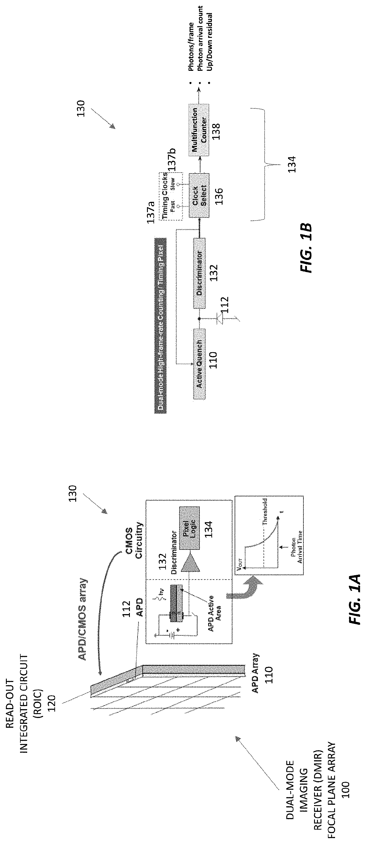
[0030]A dual-mode imaging receiver (DMIR) includes a focal plane array (FPA) and read-out integrated circuit (ROIC) enabling individual pixels to be switched between imaging and communications modes. The ROIC detects, demodulates, and reads data at each pixel with an off-chip bandwidth proportional to the number of pixels receiving active communication signals rather than the total number of pixels in the FPA. Each pixel operates independently, so the DMIR can simultaneously detect many communications signals from different angle in wide area field of view. As the signal sources move with respect to the DMIR, the signals are picked up by different pixels in the DMIR, eliminating the need for precision steering or scanning of the DMIR. This makes the DMIR smaller, lighter, and less power hungry than a conventional narrow-beam free-space optical communications receiver with a precision gimbal for pointing, acquisition, and tracking. The DMIR can be integrated with an agile-beam laser ...


PUM


Abstract

A dual-mode imaging receiver (DMIR) can acquire and maintain SOA free-space optical communication (FSOC) links without a precision mechanical gimbal. Unlike other FSOC technologies, a DMIR can operate without precise spatial alignment and calibration of the transmitter's or receiver's spatial encoders (precision pointing) in static (fixed point to point) geometries. Instead, a DMIR uses electronic receive beam selection to acquire and track transmitters with coarse mechanical pointing and a single aperture. And because the DMIR can operate with just one aperture, it does not need a beacon at the transmitter since it does not transition from a wide field-of-view acquisition aperture to a narrow field-of-view detection and decoding aperture even in dynamic geometries.

Description

CROSS-REFERENCE TO RELATED APPLICATION(S)[0001]This application claims the priority benefit, under 35 U.S.C. § 119(e), of U.S. Application No. 62 / 551,968, entitled “Dual Mode Imaging Receiver,” which was filed on Aug. 30, 2017, and is incorporated herein by reference in its entirety.GOVERNMENT SUPPORT[0002]This invention was made with Government support under Contract No. FA8721-05-D-0001 awarded by the U.S. Air Force. The Government has certain rights in the invention.BACKGROUND[0003]State-of-the-art (SOA) optical communication link efficiencies are bumping against the theoretical limits of channel capacity, with more than one demonstration of links transferring data reliably at an average rate of several bits per detected photon. However, despite the great strides in link efficiency, conventional receiver pointing, acquisition, and tracking (PAT) implementations are often complex, and the size weight and power (SWaP) of PAT subsystems is often a barrier to adoption of optical comm...

Claims


Application Information

Patent Timeline
Patent Type & Authority Patents(United States)
IPC IPC(8): G01T1/24H04B10/11H04N5/3745H04B10/112G01J1/44H04N7/22H04N5/341H04N5/225H04B10/60
CPCH04B10/60H04N5/2259H04N5/3415G01T1/24H04N5/2258H04N7/22H04N5/37455H04B10/11G01J2001/442H04B10/1121H04N25/772H04N23/45H04N23/58H04N25/41
Inventor SHAW, GARY A.CANDELL, LAWRENCE M.HOPMAN, PABLO I.
Owner MASSACHUSETTS INST OF TECH
Learn More