Method and device for generating a microscopy panoramic representation

a microscopy and panoramic technology, applied in the field of generating a microscopy panoramic representation, can solve the problems of low spreading of these concepts, low cost of such digital slide scanners, and inability to visualize panoramas in real time, and achieve the effect of minimizing the error as regards the arrangement of microscopy pictures among one another

Active Publication Date: 2020-03-03
FRAUNHOFER GESELLSCHAFT ZUR FOERDERUNG DER ANGEWANDTEN FORSCHUNG EV
View PDF7 Cites 2 Cited by
  • Summary
  • Abstract
  • Description
  • Claims
  • Application Information

AI Technical Summary

Benefits of technology

[0010]According to an embodiment, a method for generating a microscopy panoramic representation of a three-dimensional sample having a lateral extension in the x and y directions may have the steps of: a) arranging the three-dimensional sample on a positioner; b) recording the sample by means of an imaging device in order to obtain a first microscopy picture of the sample having a first section; c) altering the perspective onto the two-dimensional sample in the z direction; d) recording the sample by means of the imaging device in order to obtain a second microscopy picture of the sample having a second section; e) determining change information which allows drawing conclusions as to the change in perspective in the z direction, using a difference between the first and second microscopy pictures; and f) merging the first and second microscopy pictures while considering the change information in order to obtain the microscopy panoramic representation.
[0023]Thus, the present invention is based on the finding that several images recorded by means of a microscope (with / without motor-operated positioners, for example cross stage, linear drive, robot etc.) and using a camera, which are referred to as microscopy pictures, may be merged to one another in order to obtain a microscopy panoramic representation. There may be different sections in the image, but not necessarily. Rather, the plurality of images differs in that a change in the z direction, for example relative to the point of focus or magnification factor, has taken place while recording. Correspondingly, the above method allows combining a microscopy representation and a region thereof, for example at an increased resolution or at an altered setting of depth of focus or different focusing planes into one and the same microscopy panoramic representation, wherein the change information important for registration (that is zoom or altered focus or shifted section) may be gained directly from the stream of images. Thus, this invention also allows an interactive digitalization of large-area regions of a microscopic positioner (or other technical surfaces) without using a microscope provided with a motor or a fully automatic slide scanner. This means that the method may be employed by commercially available microscopes and digital cameras. Compared to the known technology, this variation is considerably cheaper and is also easy to integrate into existing microscope workplaces, which allows an improved digitalization of the specimens and easier documentation of the sample.

Problems solved by technology

However, the costs for such digital slide scanners are relatively high, thereby entailing a still low spreading of these concepts.
Using such software which generates microscopy panoramic representations offline, however, a disadvantage is that the panoramas cannot be visualized in real time.
The consequence of this is that it is hard for the user to recognize whether he or she is taking a complete panorama or whether “holes” or “white tiles” remain in the image.
In addition, consequently the user cannot perform corrections in case the images taken have not been merged correctly.
However, usually only individual images but not large-area-regions can be acquired and documented at high a resolution.

Method used


Image

  • Method and device for generating a microscopy panoramic representation
  • Method and device for generating a microscopy panoramic representation
  • Method and device for generating a microscopy panoramic representation

Examples


Embodiment Construction

[0041]Before discussing below embodiments of the present invention referring to the figures, it is to be pointed out that same elements and structures are provided with same reference numerals such that the description thereof is mutually applicable or exchangeable.

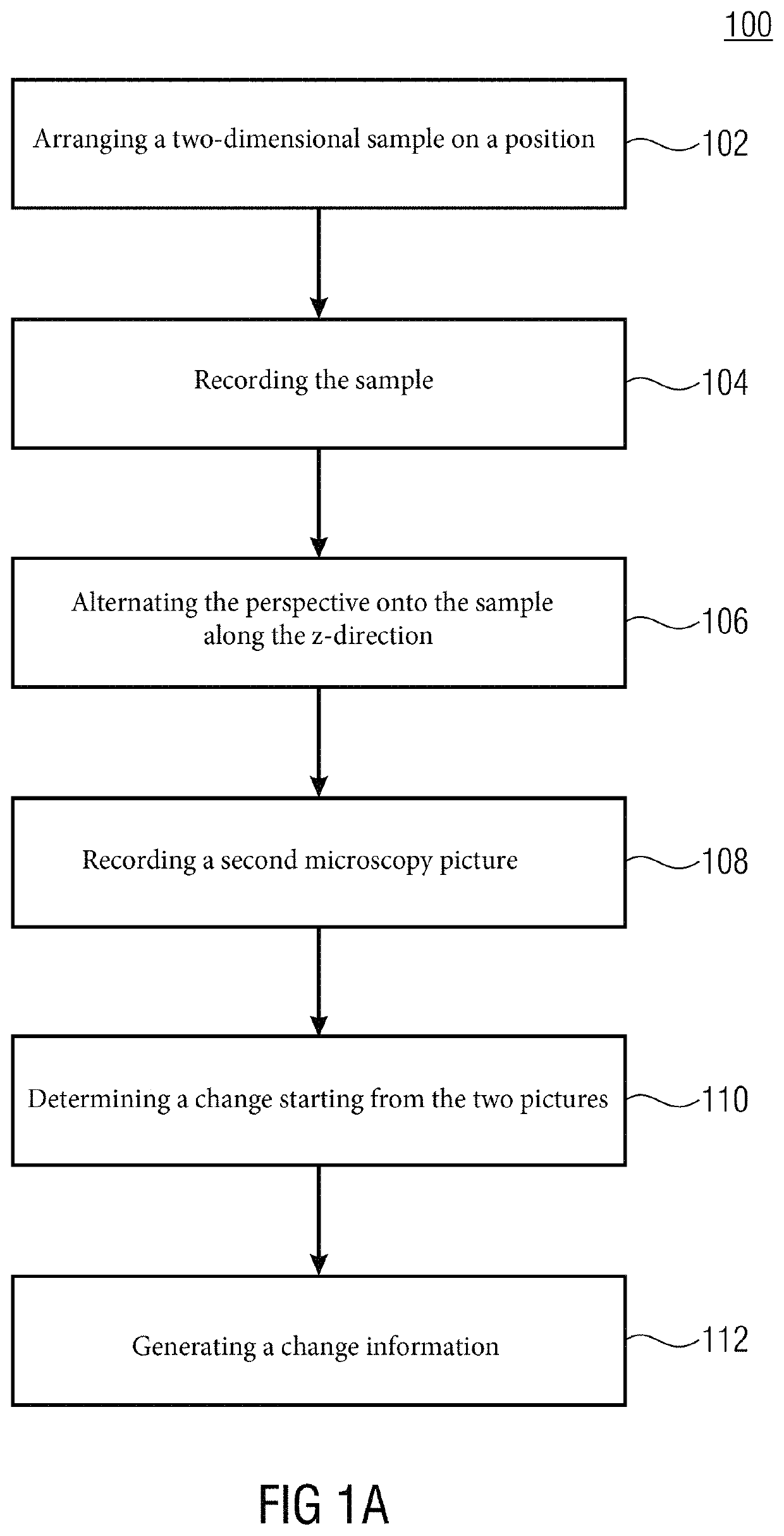
[0042]FIG. 1a shows the method for generating a microscopy representation 100. The method 100 comprises the six basic steps 102-112 which will be discussed below in particular referring to FIG. 1b, but also FIG. 1c.

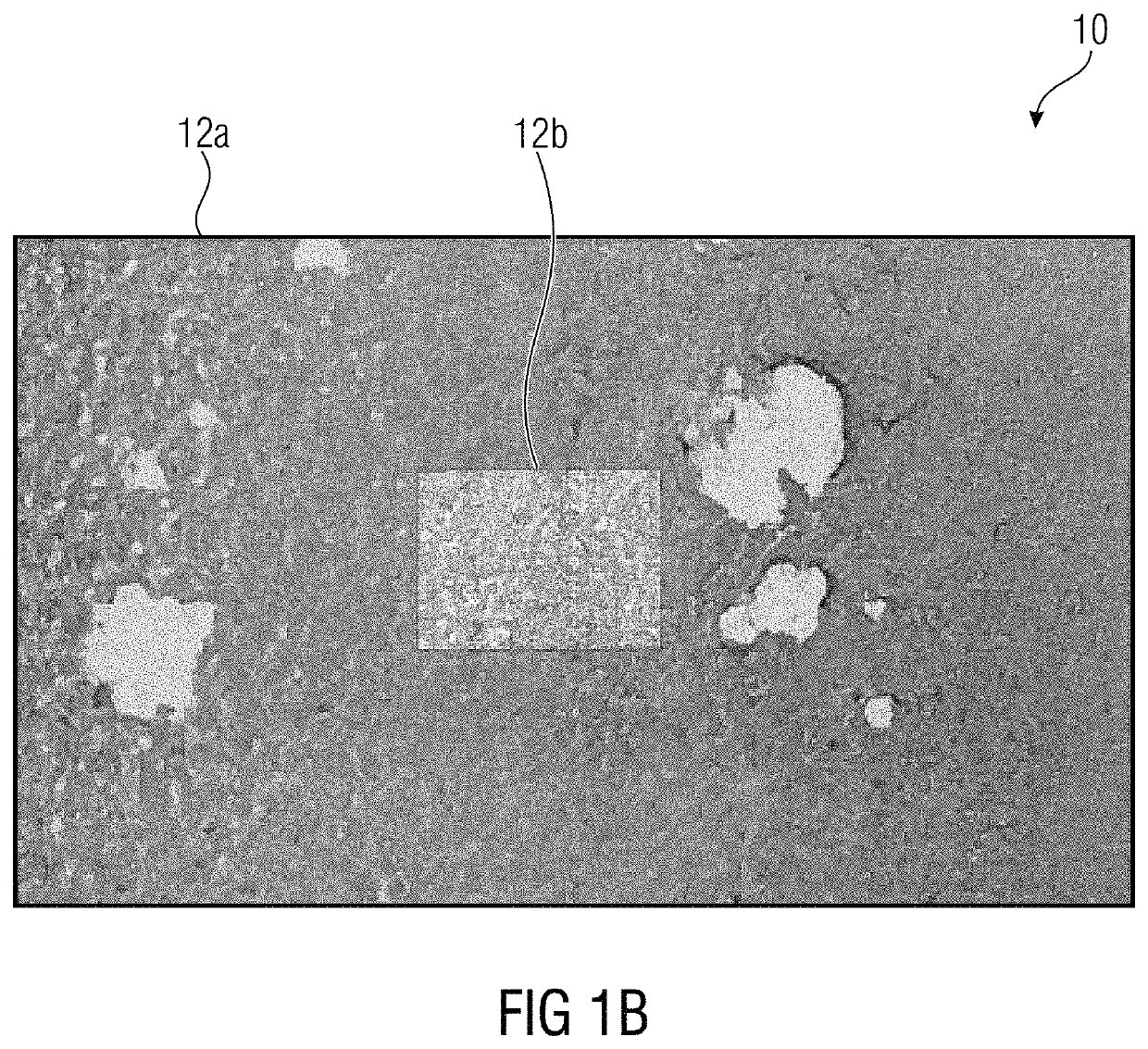
[0043]FIG. 1b shows a microscopy panoramic representation 10 comprising the microscopy representations 12a and 12b which are merged into each other so as to form the total microscopy panoramic representation 10. The microscopy pictures 12a and 12b are obtained by means of an imaging device, such as, for example, a camera using a microscope. Typically, samples which are present as a two-dimensional element (that is having an area) are examined using microscopes. Frequently, due to their lateral extensions, x an...


PUM


Abstract

Embodiments of the present invention relate to a method for generating a microscopy representation of a three-dimensional sample having a lateral extension in the x and y directions. The method has the following steps: a) arranging the flat three-dimensional sample on a positioner; b) recording the sample by means of an imaging device to obtain a first microscopy picture of the sample having a first section; c) altering the perspective onto the two-dimensional sample in the z direction; d) recording the sample by means of the imaging device to obtain a second microscopy picture of the sample having a second section; e) determining change information which allows drawing conclusions as to the change in perspective in the z direction, using a difference between the first and second microscopy pictures; and f) merging the first and second microscopy pictures while considering the change information to obtain the microscopy panoramic representation.

Description

CROSS-REFERENCE TO RELATED APPLICATION[0001]This application claims priority from German Application No. 10 2015 219 971.1, which was filed on Oct. 14, 2015, which is incorporated herein in its entirety by this reference thereto.BACKGROUND OF THE INVENTION[0002]Embodiments of the present invention relate to a method for generating a microscopy panoramic representation, and to a corresponding computer program. Further embodiments relate to a device for generating a microscopy panoramic representation, and to a system including the device and a microscope. Generally, the context of the invention is in the field of image analysis and visualization for microscopy.[0003]Microscopy is used in particular in the medical field. In clinical laboratories and pathology departments, tissue, cells and body fluids are examined, that is evaluated visually under a microscope, every day. Depending on the size of the laboratory or department, these may be a few dozen up to several 1000 microscope slid...

Claims


Application Information

Patent Timeline
Patent Type & Authority Patents(United States)
IPC IPC(8): H04N9/47G06T3/40H04N13/117G06T7/11G02B21/36G06K9/62G06T5/50H04N5/232
CPCG06T3/4038G06T7/11G06K9/6201H04N13/117G06T3/4053G02B21/367G06T5/50H04N5/23238G06T2207/20112G06T2207/10056G06F18/22H04N23/698
Inventor MUENZENMAYER, CHRISTIANGRYANIK, ALEXANDERBERGEN, TOBIASWITTENBERG, THOMAS
Owner FRAUNHOFER GESELLSCHAFT ZUR FOERDERUNG DER ANGEWANDTEN FORSCHUNG EV
Why Eureka
Try Eureka