
High-capacity stacked-electrode metal-ion accumulator capable of delivering high power

a metal-ion accumulator, high-capacity technology, applied in the direction of cell components, final product manufacturing, sustainable manufacturing/processing, etc., can solve the problems of reducing affecting the efficiency of the electrochemical generator, so as to achieve the effect of reducing mechanical stresses in the thickness of the electrode of higher porosity, reducing the internal assembly, and improving the energy density per unit volum

Active Publication Date: 2020-03-10
COMMISSARIAT A LENERGIE ATOMIQUE ET AUX ENERGIES ALTERNATIVES
View PDF11 Cites 0 Cited by
  • Summary
  • Abstract
  • Description
  • Claims
  • Application Information

AI Technical Summary

Benefits of technology

The patent text describes a way to improve the performance of prismatic accumulators by making the electrodes in one polarity have higher porosity. This allows for faster current drainage and reduces the energy lost through ionic resistance. By doing this, the thickness of the active insertion material is reduced, except in areas that may be subject to significant thermal conditions during the accumulator's life. Overall, this improves the efficiency and performance of prismatic accumulators.

Problems solved by technology

The major drawback of these flexible shells is that their tightness is seriously degraded over time because of the lack of chemical strength of the sealing that is provided.
Although they are satisfactory in many respects, stacked-electrode Li-ion accumulators of prismatic shape, particularly those of high capacity capable of delivering high power, give rise to major problems of heat dissipation, due to their intrinsic design.
This configuration may then be more space-consuming, thereby reducing the energy density per unit of volume (in Wh / liter) of the battery as a whole.
The inventors have conducted comparative tests to demonstrate the usefulness of this solution, but also the limitations that exist on the use of present-day accumulators with a high total thickness, because of the heating that they create.
To summarize, stacked-electrode prismatic Li-ion accumulators, and more generally metal-ion accumulators, notably those with high capacity, are subject to limits in their design.
A first design limit is a large thickness, because, above a certain value of thickness, localized heating occurs, causing reduced life and lower performance, with, notably, a high risk of electrical and safety malfunction.

Method used


Image

  • High-capacity stacked-electrode metal-ion accumulator capable of delivering high power
  • High-capacity stacked-electrode metal-ion accumulator capable of delivering high power
  • High-capacity stacked-electrode metal-ion accumulator capable of delivering high power

Examples


Embodiment Construction

[0135]Other advantages and characteristics of the invention will be more apparent from a perusal of the detailed description of examples of embodiment of the invention, provided by way of non-limiting illustration, with reference to the following drawings, in which:

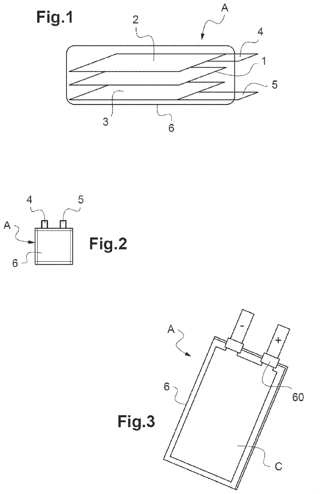
[0136]FIG. 1 is a schematic exploded perspective view showing the different elements of a lithium-ion accumulator,

[0137]FIG. 2 is a face-on view showing a lithium-ion accumulator with its flexible shell according to the prior art,

[0138]FIG. 3 is a perspective view of an example of a lithium-ion accumulator according to the prior art with its flexible shell;

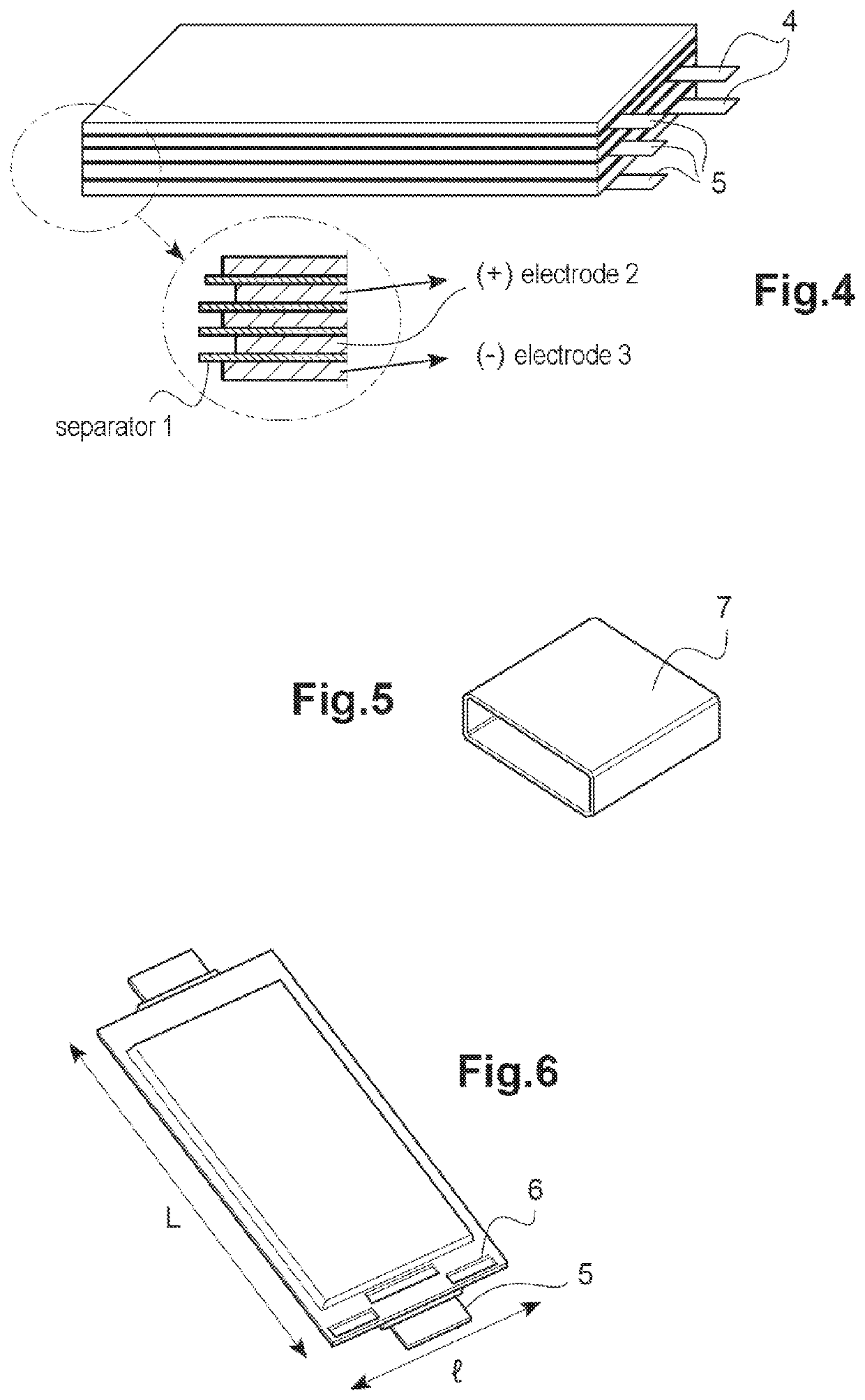
[0139]FIG. 4 is a perspective view of a stacked-electrode prismatic lithium-ion accumulator according to the prior art;

[0140]FIG. 5 is a perspective view showing a rigid casing to house a prismatic accumulator according to FIG. 5;

[0141]FIG. 6 is a perspective view of another example of a lithium-ion accumulator according to the prior art with its flexible shell, before ...


PUM

PropertyMeasurementUnit
porosityaaaaaaaaaa
porosityaaaaaaaaaa
porosityaaaaaaaaaa

Abstract

The present invention relates to a metal-ion accumulator (A), comprising a stack of elementary electrochemical cells, each comprising a cathode (2), an anode (3), and a separator (1) impregnated with electrolyte intercalated between the anode and the cathode, each anode and cathode consisting of a substrate (2S, 3S) formed from a metal foil comprising a central portion (22, 32) supporting, on at least one of its main faces, a layer of active metal ion insertion material, the porosity of the layers of active material of the electrodes of one of the given polarities (anode or cathode) having at least two different values in the stack, the highest porosity being that of at least one electrode of said polarity, arranged between the center and the ends of the stack.

Description

CROSS-REFERENCE TO RELATED APPLICATIONS[0001]This application claims priority to French Patent Application 16 61413, filed on Nov. 23, 2016, which is incorporated herein by reference in its entirety for all purposes.TECHNICAL FIELD[0002]The present invention relates to the field of metal-ion electrochemical generators, which operate according to the principle of insertion or extraction, in other words intercalation and deintercalation, of metal ions in at least one electrode.[0003]More particularly, it relates to a metal-ion electrochemical accumulator comprising a stack of elementary electrochemical cells, each comprising an anode, a cathode, and a separator impregnated with electrolyte intercalated between the anode and the cathode, two current collectors, of which one is connected to the anode and the other to the cathode, and a shell whose shape is elongated along a longitudinal axis, the shell being arranged to house the electrochemical cells in a sealed manner while allowing t...

Claims


Application Information

Patent Timeline
Patent Type & Authority Patents(United States)
IPC IPC(8): H01M2/02H01M4/48H01M10/0525H01M4/485H01M10/0585H01M10/613H01M10/647H01M10/654H01M4/02H01M50/119
CPCH01M4/485H01M2/0257H01M10/0585H01M4/48H01M2/0285H01M10/0525H01M2/0217H01M2004/027H01M10/654H01M10/647H01M2004/028H01M10/613Y02E60/10H01M50/103Y02P70/50H01M50/119
Inventor DEWULF, FRÉDÉRICCHAMI, MARIANNE
Owner COMMISSARIAT A LENERGIE ATOMIQUE ET AUX ENERGIES ALTERNATIVES
Learn More