Device and method for transporting preforms in the region of a blow-molding machine

a technology of blow-molding machine and preform, which is applied in the direction of domestic applications, other domestic articles, domestic articles, etc., can solve the problems of multiple preforms, unsuitable for further processing, and ejection at the same time, so as to prevent the ejection of preforms at the unforeseen time, the effect of high speed

Active Publication Date: 2020-03-17
KHS GMBH
View PDF26 Cites 0 Cited by
  • Summary
  • Abstract
  • Description
  • Claims
  • Application Information

AI Technical Summary

Benefits of technology

[0014]With this in mind, the object of this invention is therefore to provide devices and methods that are improved compared to the existing state of the art, and which support a careful conveyance of preforms in the region of a blow-molding machine at high speeds and prevent the unforeseen ejection of preforms that are suitable for further processing.

Problems solved by technology

The described type of ejection mechanics has the disadvantage that multiple preforms that are hanging between the guide collar and the transport wheel are ejected at the same time.
This means that not only are preforms that are unsuitable for further processing ejected, but rather also fully intact preforms that are properly suitable for the manufacture of containers.
The described ejection mechanics does not however only lead to the unnecessary ejection of properly suitable preforms, but rather also leads to a delay in the further conveyance of the preforms.
Time-consuming outward and inward pivoting motions of such ejection mechanics are undesirable, in particular, when working at high process speeds, in which multiple preforms per second are blown out to containers.
It has also been shown that an inspection of the preforms that are conveyed in a hanging position between the transport wheel and a restraining collar that is radially arranged at the start of the transport wheel, are at times difficult to inspect for defects or irregularities.
There is furthermore undesirable mechanical friction between the guide collar that is arranged on the perimeter of the transport wheel and the preform, which requires increased energy expenditure for the conveyance of the preforms and leaves behind friction marks on the preforms.
It is also disadvantageous that it leads to wear and tear of the guide collar surfaces.

Method used


Image

  • Device and method for transporting preforms in the region of a blow-molding machine
  • Device and method for transporting preforms in the region of a blow-molding machine
  • Device and method for transporting preforms in the region of a blow-molding machine

Examples


Embodiment Construction

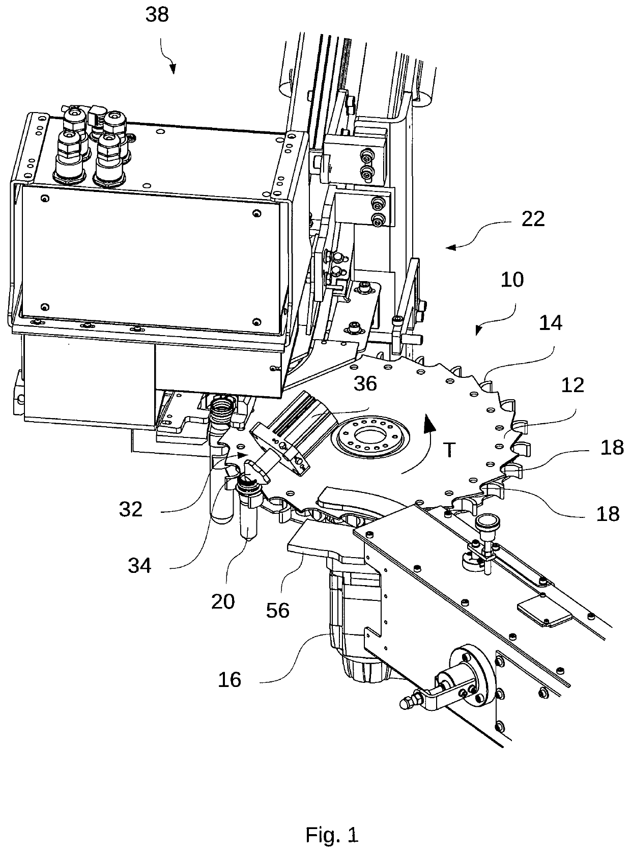
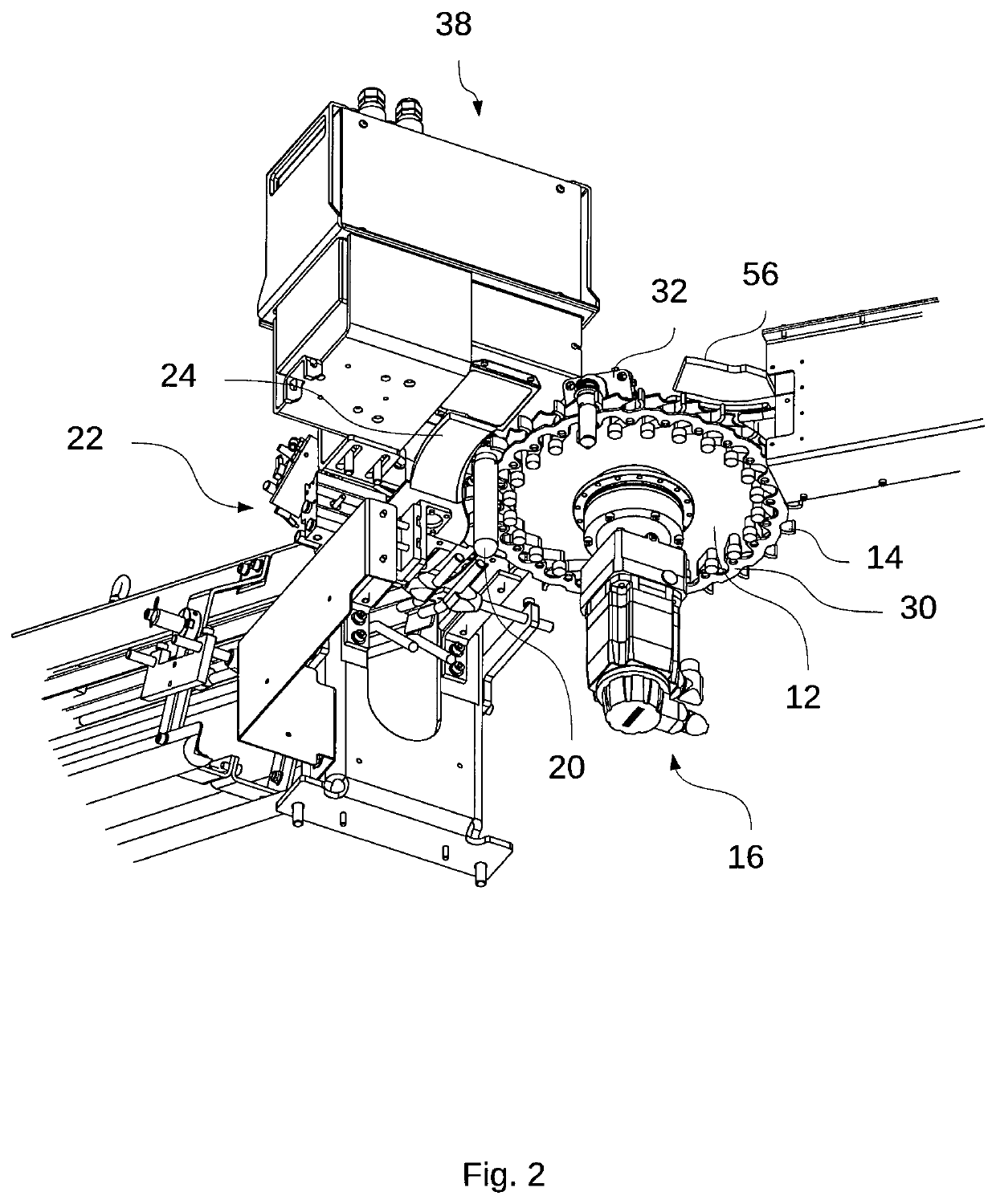
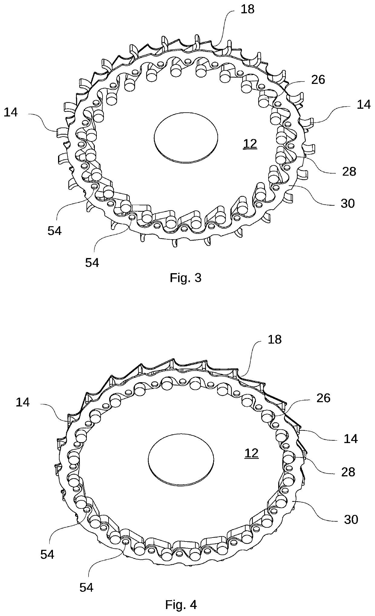
[0055]FIG. 1 is an isometric representation of a transport device 10 according to the invention with a planar rotating transport wheel 12 and an ejection unit 32. Furthermore, there is an inspection device 38, an inlet area 22 as well as a guide rail 56 that are represented. The rotational direction of the transport wheel 12 that is foreseen for the transport of the preforms 20 is indicated with the directional arrow T.

[0056]The ejection unit 32 is arranged in the foreground from the illustration perspective, on top of the transport wheel 12. The ejection unit 32 has an ejection ram 34 that thrusts longitudinally from a drive 36. The ejection unit 32 is preferentially mounted to a carrier structure of the transport device 10, in particular, in a non-rotatable manner in comparison to the transport wheel 12. For simplification of the illustration and for better clarity—as in other portions of the illustrations—the representation of the carrier structure was omitted, which is to say, f...


PUM

PropertyMeasurementUnit
areaaaaaaaaaaa
rotational movementaaaaaaaaaa
timeaaaaaaaaaa

Abstract

The invention relates to devices and methods for transporting preforms (2) made of a thermoplastic material in the region of a blow-molding (10), having a transport wheel (12) which is mounted in a rotatable manner about a rotational axis and which comprises multiple receiving recess (18) distributed in the circumferential direction over the circumference of the transport wheel for receiving and conveying preforms (20). A hook element (14) is arranged on the transport wheel (12) in the region of each receiving recess (18), said hook element being mounted on the transport wheel (12) in a pivotal manner between an open position and a closed position, and in the closed position, the hook element (14) secures a preform (20) to be transported in the respective receiving recess (18) from falling out of the receiving recess (18).

Description

CROSS-REFERENCE TO RELATED APPLICATIONS[0001]This application is a U.S. National Stage of PCT / EP2016 / 000078, filed Jan. 18, 2016, and claims priority to DE 10 2015 000 631.2, filed Jan. 22, 2015.STATEMENT REGARDING FEDERALLY SPONSORED RESEARCH OR DEVELOPMENT[0002]Not applicable.THE NAMES OF THE PARTIES TO A JOINT RESEARCH AGREEMENT[0003]Not applicable.INCORPORATION-BY-REFERENCE OF MATERIAL SUBMITTED ON A COMPACT DISC OR AS A TEXT FILE VIA THE OFFICE ELECTRONIC FILING SYSTEM (EFS-WEB)[0004]Not applicable.STATEMENT REGARDING PRIOR DISCLOSURES BY THE INVENTOR OR A JOINT INVENTOR[0005]Not applicable.BACKGROUND OF INVENTIONField of Invention[0006]The present invention refers to a transport device, a method, a transport system and a blow-molding machine for the blow-molding of containers made of a thermoplastic material.Brief Description of Related Art[0007]During container molding by blow pressure action, preforms made of a thermoplastic material, for example, made of PET (polyethylene t...

Claims


Application Information

Patent Timeline
Patent Type & Authority Patents(United States)
IPC IPC(8): B29C49/42B29C49/78B29C49/06B29L31/00
CPCB29C49/4252B29C49/4205B29C49/78B29C49/06B29C2949/78773B29L2031/7158B29C49/42075B29C49/42095B29C49/4238B29C2049/023B29C2949/0715
Inventor LINKE, MICHAELBAUMGARTE, ROLFKLATT, DIETERLEWIN, FRANK
Owner KHS GMBH
Why Eureka
Try Eureka