Impedance tube having a machined union

a technology of impedance tube and union, which is applied in the direction of machines/engines, lighting and heating apparatus, instruments, etc., can solve the problems of high cycle fatigue of the combinator, high cost and sensitive dynamic sensors, and the difficulty of the sensor connected to the small inner diameter waveguide to sensing high frequencies

Active Publication Date: 2020-03-17
DOOSAN HEAVY IND & CONSTR CO LTD
View PDF8 Cites 0 Cited by
  • Summary
  • Abstract
  • Description
  • Claims
  • Application Information

AI Technical Summary

Problems solved by technology

When the combustion occurs in the combustor to make a combusted gas, the combustion is under high-temperature and high-pressure conditions; thus the combustor is susceptible to High Cycle Fatigue (HCF) resulting from the combustion dynamics.
The state of the art impedance tube including a dynamic sensor comprises a waveguide having an inner diameter of ⅛ inch for routing because a space to install the dynamic sensor is not available and the dynamic sensor is expensive and sensitive to several factors.
However, the dynamic sensor connected to the small inner diameter waveguide has difficulty in sensing high frequencies due to excessive damping.

Method used


Image

  • Impedance tube having a machined union
  • Impedance tube having a machined union
  • Impedance tube having a machined union

Examples


embodiment 1

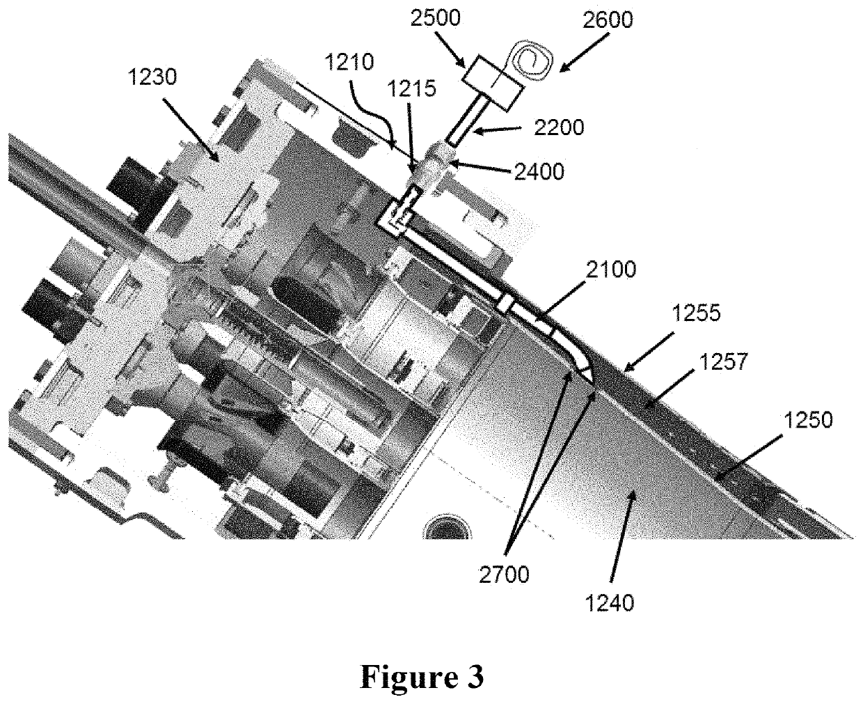
[0031]An impedance tube, comprising:

[0032]a machined union including a first channel and a second channel;

[0033]a first tube connected to the first channel of the machined union;

[0034]a second tube connected to the second channel of the machined union;

[0035]a sensor housing including a sensor and connected to the second tube; and

[0036]an infinite tube connected to the sensor housing;

[0037]wherein the second channel includes a channel thread, and

[0038]wherein a threaded end of the second tube is coupled with the channel thread of the second channel.

embodiment 2

[0039]The impedance tube according to embodiment 1, wherein the first tube is attached to the machined union through a weld.

embodiment 3

[0040]The impedance tube according to any of embodiments 1-2, further comprising a compression fitting, wherein the second tube passes through the compression fitting.


PUM

PropertyMeasurementUnit
lengthaaaaaaaaaa
impedanceaaaaaaaaaa
inner diameteraaaaaaaaaa

Abstract

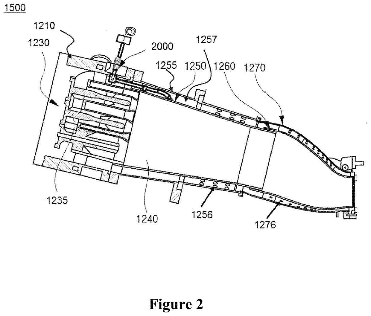
A combustion system can include: a liner defining a combustion chamber; a casing covering the combustion chamber; a first tube disposed in the liner; a machined union disposed inside the casing and connected to the first tube; a second tube passing through the casing and connected to the machined union; a sensor housing disposed outside the casing and connected to the second tube; and an infinite tube connected to the sensor housing.

Description

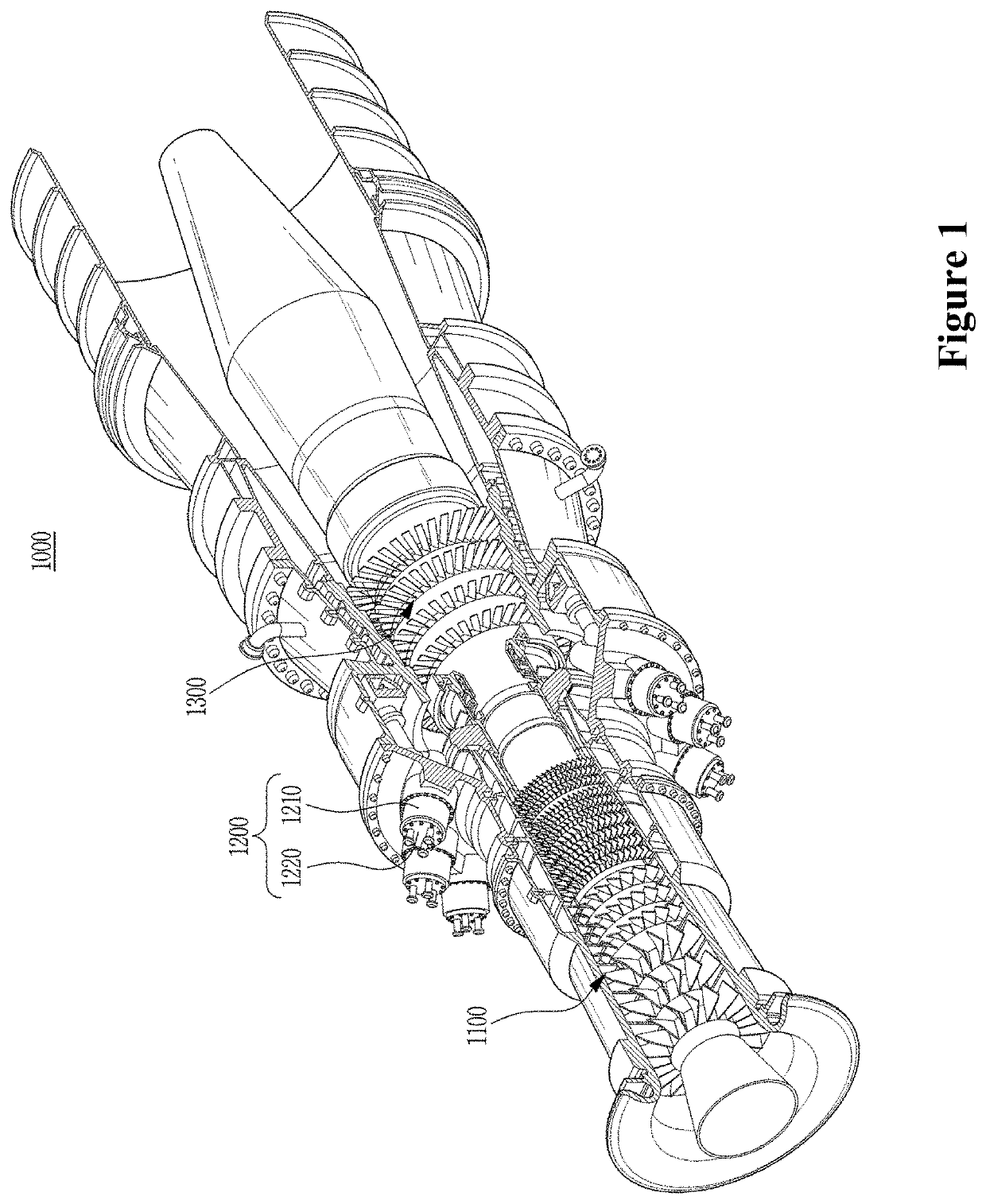
BACKGROUND OF INVENTION[0001]A gas turbine generally comprises a compressor, a combustor, and a turbine. The compressor provides compressed air generated by a plurality of compressor blades to the combustor, wherein the compressed air is high-temperature and high-pressure air. The combustor mixes the compressed air, introduced from the compressor, with fuel and combusts the mixed air. The combusted gas generated from the combustor is discharged to the turbine and the turbine is rotated by the combusted gas, thereby generating power. The generated power is used in various fields such as for the generation of electricity and to drive machinery. The gas turbine is used to drive a generator, an aircraft, a locomotive, and the like.[0002]When the combustion occurs in the combustor to make a combusted gas, the combustion is under high-temperature and high-pressure conditions; thus the combustor is susceptible to High Cycle Fatigue (HCF) resulting from the combustion dynamics. The combusto...

Claims


Application Information

Patent Timeline
Patent Type & Authority Patents(United States)
IPC IPC(8): F01D21/14F01D21/00G01L19/08G01L19/14G01L19/00
CPCF01D21/14G01L19/0007G01L19/142F01D21/003G01L19/086F05D2260/80F01D17/02F05D2240/35F23R3/00F23R2900/00013F23R2900/00014F23R2900/00017F05D2230/232F23R3/002
Inventor ABU-IRSHAID, ESAMSPENCE, KEVIN JAMES
Owner DOOSAN HEAVY IND & CONSTR CO LTD
Why Eureka
Try Eureka