Optical laminate, polarizer, and display apparatus

a technology of optical laminates and polarizers, applied in the field of optical laminates, can solve the problems of disadvantageous cost-benefit multi-layer arrangement and deterioration of anti-glare properties, and achieve the effects of maintaining anti-glare properties, reducing cost, and reducing the effect of glar

Active Publication Date: 2020-03-17
TOPPAN TOMOEGAWA OPTICAL FILM CO LTD
View PDF28 Cites 0 Cited by
  • Summary
  • Abstract
  • Description
  • Claims
  • Application Information

AI Technical Summary

Benefits of technology

[0009]Therefore, it is an object of the present disclosure to provide an optical laminate that can suppress dazzle while maintaining the anti-glare properties and contrast thereof when applied to image display panels, particularly an image display panel having a high resolution of not lower than 200 ppi, and a polarizer and image display apparatus including the optical laminate.
[0013]According to the present disclosure, an optical laminate that can suppress dazzle while maintaining the anti-glare properties and contrast thereof even when applied to an image display panel having a high resolution of not lower than 200 ppi, and a polarizer and an image display apparatus including the optical laminate, can be provided.

Problems solved by technology

In this case, as the concave-convex size increases, the anti-glare properties increase, but the anti-dazzle properties deteriorate due to an increase in the lens effect.
However, the resultant multilayer arrangement is disadvantageous in terms of cost.
Since the resolution of image display panels has been increasing in recent years, the anti-dazzle properties of existing anti-glare films are not sufficient, and therefore, there is a demand for an anti-glare film having improved anti-dazzle properties while maintaining the anti-glare properties and contrast thereof.

Method used


Image

  • Optical laminate, polarizer, and display apparatus
  • Optical laminate, polarizer, and display apparatus
  • Optical laminate, polarizer, and display apparatus

Examples


examples

[0061]Examples in which an optical laminate according to the embodiment is specifically implemented or carried out will now be described.

[0062](Production Method for Optical Laminate)

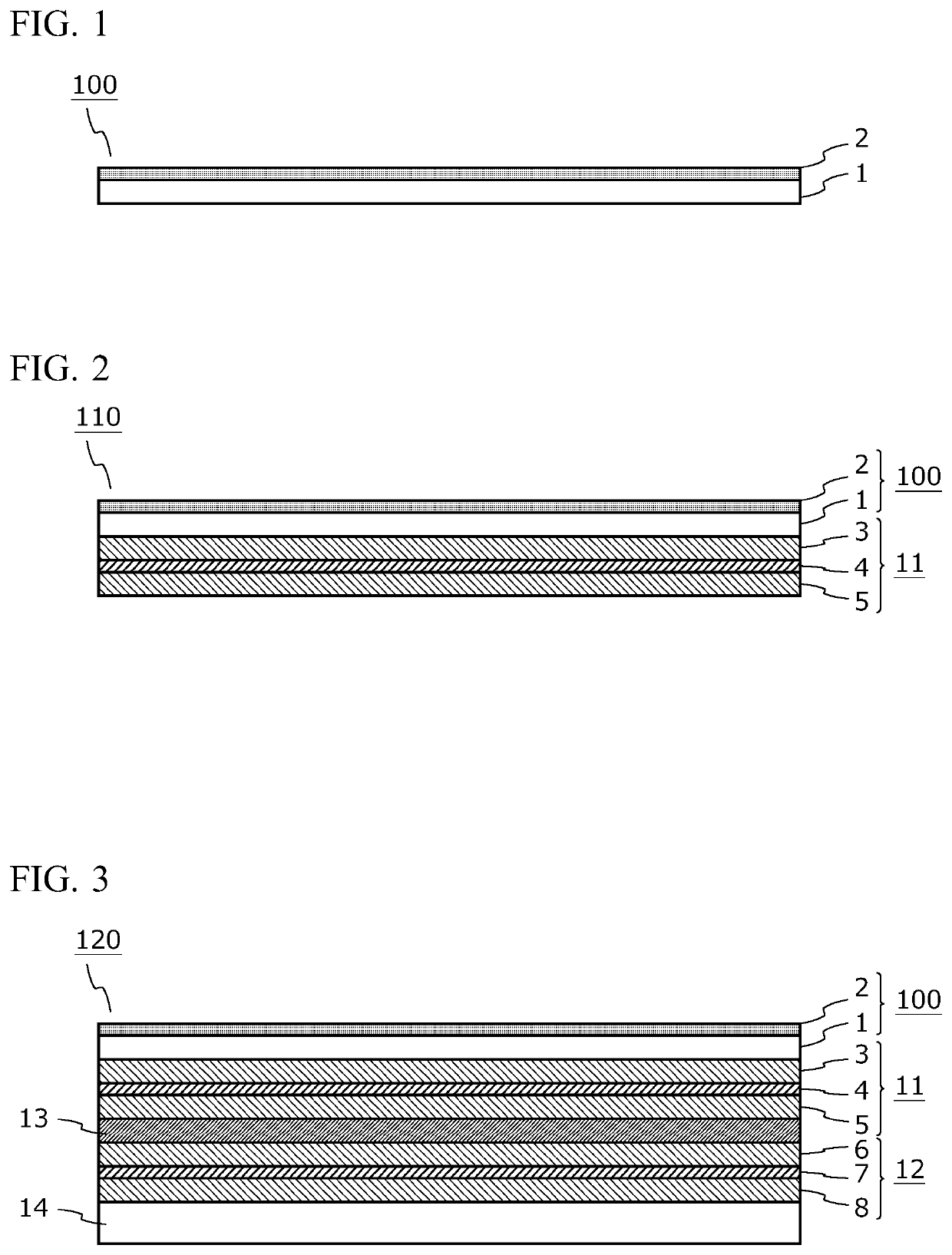
[0063]A coating liquid for forming an optical functional layer that contains materials described below at proportions shown in Tables 1 and 2 was formulated. The formulated coating liquid was applied to a triacetylcellulose film (translucent substrate) having a thickness of 40 μm. The resultant coating film was dried (the solvent was vaporized). Thereafter, the resultant coating film was caused to undergo polymerization so that the coating film is cured to form an optical functional layer. Thus, optical laminates according to Examples 1 to 13 and Comparative examples 1 to 8 were obtained. Note that, in Table 1, “-” indicates that the corresponding material is not blended.

[0064][Materials Used in Coating Liquid for Forming Optical Functional layer][0065]Base resin: UV / EB curable resin Light Acrylate PE-3...


PUM

PropertyMeasurementUnit
heightaaaaaaaaaa
total light transmittanceaaaaaaaaaa

Abstract

An optical laminate includes a translucent substrate, and at least one optical functional layer provided on the translucent substrate. The optical functional layer has a concave-convex shape on at least one surface. The optical functional layer contains two types of inorganic fine particles, and resin particles. The optical laminate has an internal haze X and a total haze Y satisfying (1) Y>X, (2) Y≤X+25, (3) Y≤50, and (4) 7≤X≤25. The optical laminate has a transmitted image clarity of 15% to 55% as measured using a 0.5-mm width optical comb. The number of projections having a height of not smaller than 0.1 μm is not less than 900 per mm2 of measurement area in the concave-convex shape as measured by optical interferometry at an outermost surface of the optical functional layer.

Description

CROSS REFERENCE TO RELATED APPLICATIONS[0001]This application is a continuation application of International Application No. PCT / JP2017 / 005308, filed on Feb. 14, 2017, which claims priority to Japanese Patent Application No. 2016-027340, filed on Feb. 16, 2016. The disclosures of these applications are hereby incorporated by reference.BACKGROUNDField[0002]The present disclosure relates to optical laminates suitable for anti-glare films, and polarizers and display apparatuses equipped with the optical laminates.Description of the Related Art[0003]An anti-glare film has, on its surface, a concave-convex structure which scatters external light, and thereby has anti-glare properties. The concave-convex structure on the surface of the anti-glare film is formed by the aggregation of particles (filler) in a resin layer.[0004]The anti-glare film is required to have functions such as anti-dazzle properties and high contrast in addition to anti-glare properties. The anti-glare properties, ant...

Claims


Application Information

Patent Timeline
Patent Type & Authority Patents(United States)
IPC IPC(8): G02B1/111G02F1/1335B32B7/02G02B5/02G09F9/00G02B5/30G02B1/18G02B1/16B32B27/20B32B3/30
CPCG02F1/1335G02B1/18B32B27/20G02B5/305B32B7/02G02B5/30G02B1/16G02B5/02G02B5/3041G09F9/00G02B1/111B32B3/30G02F1/133502G02F1/133504G02F1/133528B32B2307/40B32B2264/10
Inventor SERIZAWA, NAOKINAKANISHI, TAKAYUKI
Owner TOPPAN TOMOEGAWA OPTICAL FILM CO LTD
Why Eureka
Try Eureka