
Reactor

a technology of reactor and heat medium, which is applied in the direction of lighting and heating apparatus, gas-gas reaction process, laminated elements, etc., can solve the problems of increasing heat energy (input energy) of heat medium supplied to the reactor, excessive amount of steam produced, and deterioration of the energy efficiency of the entire plant, so as to reduce the temperature of raw material fluid, reduce the temperature of product, and prevent an increase in the amount of heat recovered from the product outside the reactor

Active Publication Date: 2020-03-31
IHI CORP
View PDF46 Cites 2 Cited by
  • Summary
  • Abstract
  • Description
  • Claims
  • Application Information

AI Technical Summary

Benefits of technology

The present invention provides a reactor that improves energy efficiency in an entire plant. It achieves this by using a heat recovery system to cool down the product quickly after it reaches high temperatures. This reduces the amount of heat energy that needs to be supplied to the reactor, which in turn reduces the amount of steam produced and improves overall energy efficiency. The reactor achieves this by using a raw material fluid that flows through pre-reaction channels and a heat medium that flows through main reaction channels. The heat exchange between the raw material fluid and the heat medium takes place in the pre-reactor core, where the raw material fluid is cooled and the product is preheated. This reduces the amount of heat energy needed and prevents excessive steam production, resulting in improved energy efficiency in the entire plant.

Problems solved by technology

As the amount of heat recovered from the product by the quenching drum increases, namely, as the amount of heat recovered from the product outside the reactor increases, heat energy (input energy) of the heat medium supplied to the reactor increases and an excessive amount of steam is produced.
As a result, the energy efficiency of the entire plant may deteriorate.
It is noted that not only a reactor used for a hydrogen production process but also other types of reactor have the same problems as described above.

Method used


Image

  • Reactor
  • Reactor
  • Reactor

Examples


Embodiment Construction

[0025]One embodiment and other embodiments of the present disclosure will be described below with reference to the drawings.

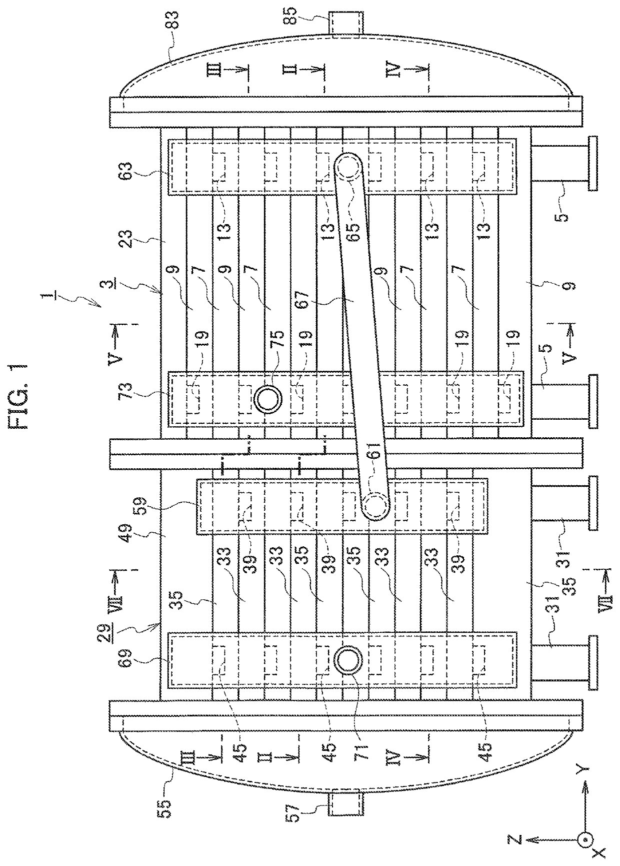
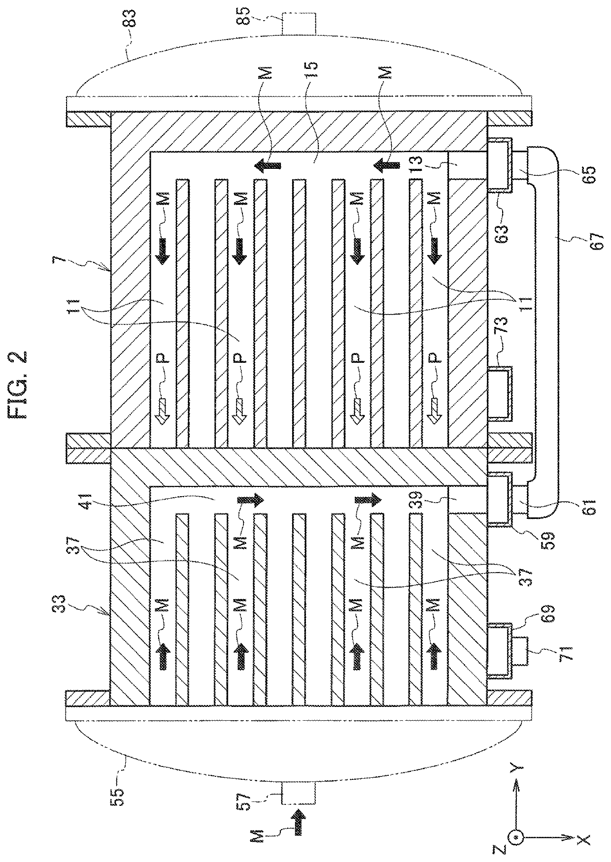
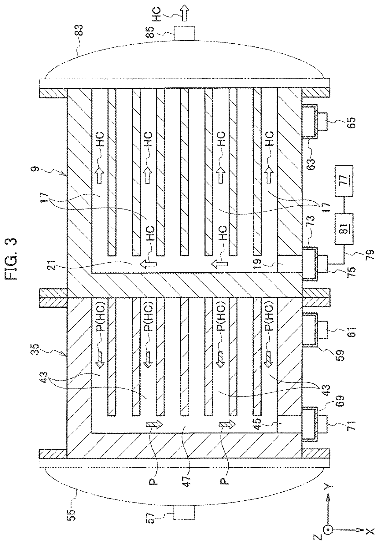
[0026]As shown in FIG. 1, a reactor 1 according to the present embodiment causes a reaction of a raw material fluid M by a heat exchange between the raw material fluid M (see FIG. 2) and a heat medium HC (see FIG. 3), so as to produce a product P (see FIG. 2). Before a specific configuration of the reactor 1 is described, the reaction of the raw material fluid M is briefly described below.

[0027]The reaction of the raw material fluid M includes two types: an endothermic reaction caused by heating the raw material fluid M and an exothermic reaction caused by cooling the raw material fluid M. Examples of the former reaction (the endothermic reaction) include a steam reforming reaction of methane as represented by the following chemical equation (1), and a dry reforming reaction of methane as represented by the following chemical equation (2)

CH4+H2O→3H2+CO  (1)

CH4+...


PUM

PropertyMeasurementUnit
temperatureaaaaaaaaaa
heightaaaaaaaaaa
heightaaaaaaaaaa

Abstract

A reactor includes: a main reactor core including main reaction flow channels through which the raw material fluid flows, and main temperature control flow channels through which the heat medium flows along a flow direction of the raw material fluid flowing in the main reaction flow channel; and a pre-reactor core including pre-reaction flow channels of which an outlet side connects with an inlet side of the main reaction flow channels and through which the raw material fluid flows, and pre-temperature control flow channels of which an inlet side connects with an outlet side of the main reaction flow channels and through which the product serving as the heat medium flows along a flow direction of the raw material fluid flowing in the pre-reaction flow channel.

Description

CROSS REFERENCE TO RELATED APPLICATIONS[0001]This application is a continuation application of International Application No. PCT / JP2016 / 066993, filed on Jun. 8, 2016, which claims priority to Japanese Patent Application No. 2015-115655, filed on Jun. 8, 2015, the entire contents of which are incorporated by reference herein.BACKGROUND1. Technical Field[0002]Embodiments described herein relate to a reactor for causing a reaction of a raw material fluid (a reaction fluid) by a heat exchange between the raw material fluid and a heat medium to generate a product (a reaction product).2. Description of the Related Art[0003]For example, a reactor used for a hydrogen production process includes a reactor core. The reactor core includes reaction flow channels through which a raw material fluid containing methane gas and steam flows, and temperature control flow channels (heating flow channels) through which a heat medium such as flue gas flows. In the configuration described above, the raw m...

Claims


Application Information

Patent Timeline
Patent Type & Authority Patents(United States)
IPC IPC(8): B01J19/24B01J19/00F28D9/00B01J12/00C07C1/04C01B3/48C01B3/38F28F3/00F28F3/04F28D21/00
CPCB01J19/249B01J19/0013F28F3/00F28F3/048C01B3/38C01B3/384C01B3/48C07C1/041B01J12/007B01J19/2485F28D9/0037B01J19/245F28D9/0093B01J2208/0053B01J2219/00159B01J2208/00212B01J2219/00094C01B2203/0283B01J2219/2414C01B2203/0883C01B2203/1241B01J2219/2453F28D2021/0022B01J2219/2467C01B2203/0238C01B2203/0233B01J2208/022B01J2219/2411B01J2219/2462C01B2203/0833B01J19/0053B01J19/24B01J2219/0054
Inventor YANO, AKIHISAOKA, TATSUYAKAMATA, HIROYUKISAKAKURA, SHIGEKIHONMA, NOBUYUKITAKEUCHI, YUSUKE
Owner IHI CORP
Learn More