Supercharge Your Innovation With Domain-Expert AI Agents!

Magnetic propulsion engine

a technology of magnetopropulsive propulsion and motor, which is applied in the direction of propulsion parts, gas pressure propulsion mounting, transportation and packaging, etc., can solve the problem of dispersing combusted pollutants into the atmospher

Active Publication Date: 2020-04-07
HESTER DAVID LEE
View PDF10 Cites 0 Cited by
  • Summary
  • Abstract
  • Description
  • Claims
  • Application Information

AI Technical Summary

Benefits of technology

The present invention is a magnetic propulsion apparatus that uses magnetic forces for propulsion without causing harmful exhaust emissions. It is designed to be a cleaner and more environmentally friendly form of propulsion. The apparatus is made up of multiple coaxial magnets placed on a non-magnetic axis rod that can adjust to various body shapes and sizes. It can be placed in the same general compartment area of the vehicle as the occupants, providing protection from external environmental conditions. The technical effects of this invention include eco-friendliness, efficient propulsion, and protection for the vehicle occupants.

Problems solved by technology

The use of hydrocarbon based fuels is generally not preferred as combustion may result in the dispersal of combusted pollutants into the atmosphere.

Method used


Image

  • Magnetic propulsion engine
  • Magnetic propulsion engine
  • Magnetic propulsion engine

Examples


Embodiment Construction

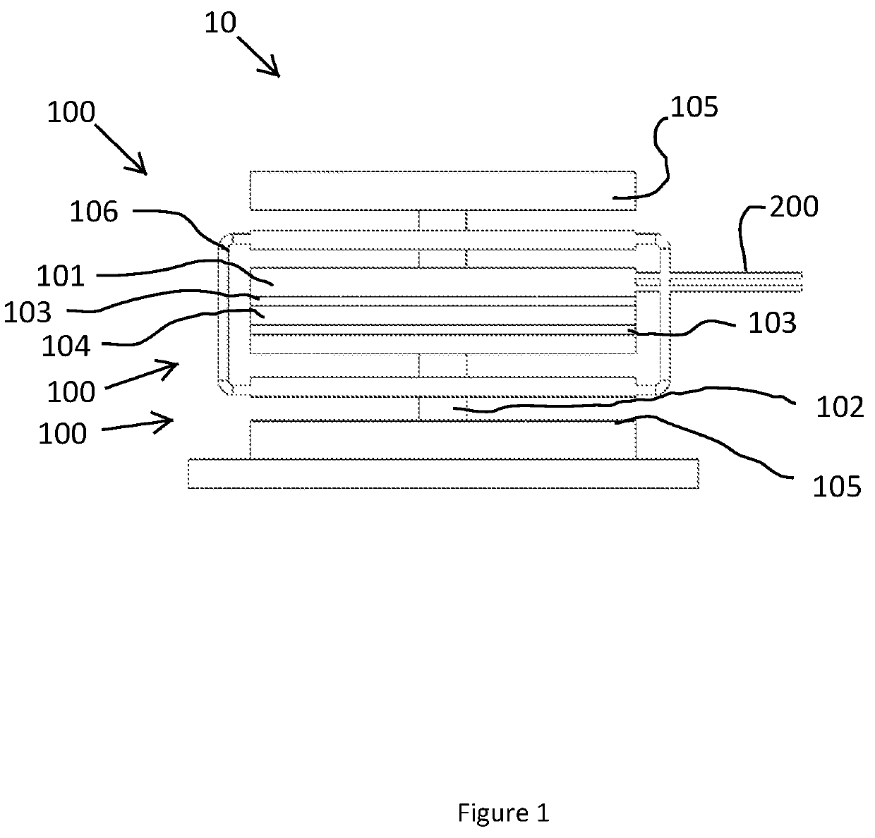
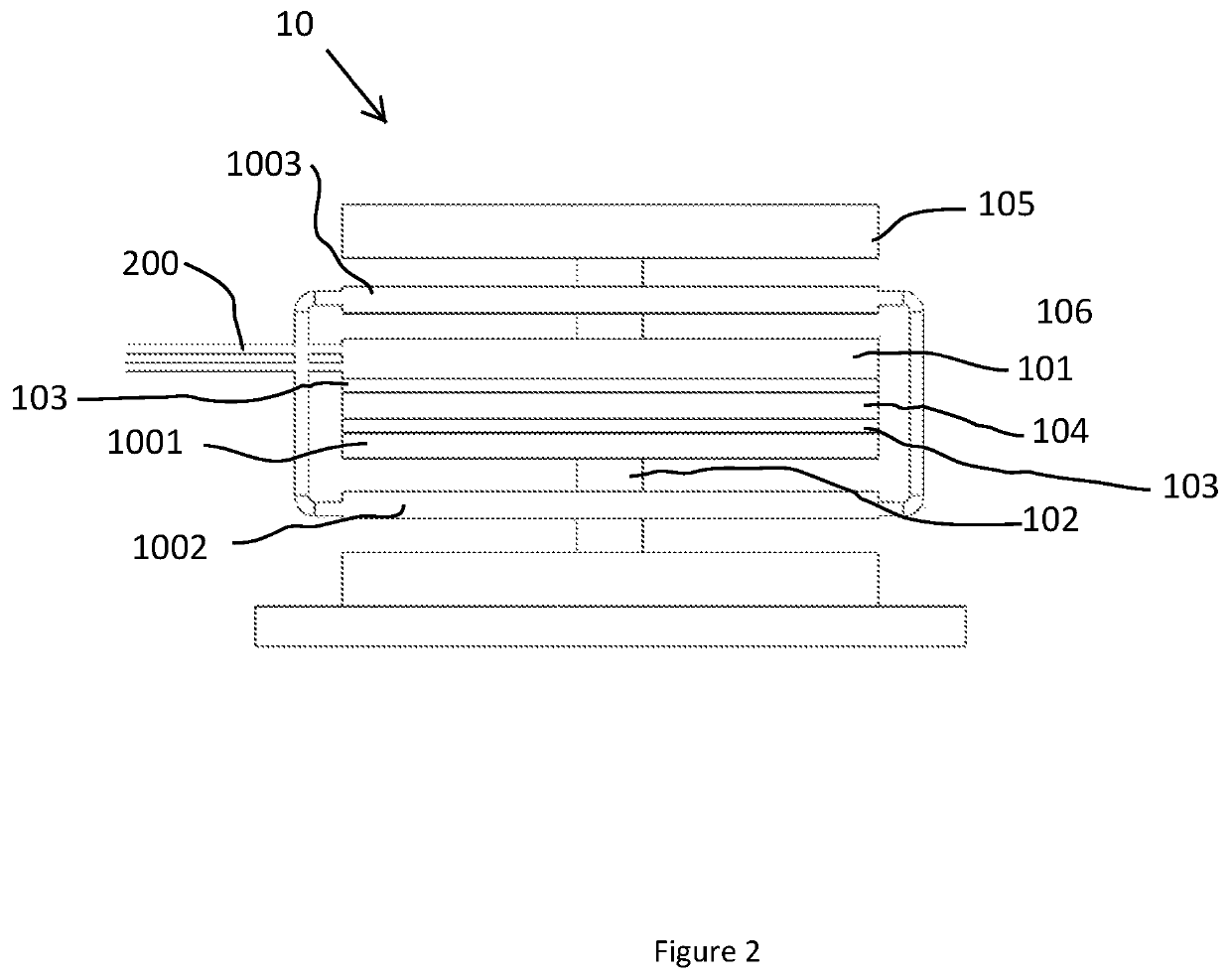
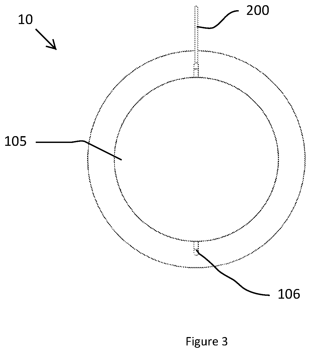
[0023]The following detailed description includes references to the accompanying drawings, which forms a part of the detailed description. The drawings show, by way of illustration, specific embodiments in which the invention may be practiced. These embodiments, which are also referred to herein as “examples,” are described in enough detail to enable those skilled in the art to practice the invention. The embodiments may be combined, other embodiments may be utilized, or structural, and logical changes may be made without departing from the scope of the present invention. The following detailed description is, therefore, not to be taken in a limiting sense.

[0024]Before the present invention is described in such detail, however, it is to be understood that this invention is not limited to particular variations set forth and may, of course, vary. Various changes may be made to the invention described and equivalents may be substituted without departing from the true spirit and scope o...


PUM


Abstract

An assembly configured to generate a propulsive force through a plurality of magnets. The assembly includes a rod having a center disk comprised of non-magnetic materials and configured to receive an electromagnet and a plurality of coaxial magnetic disks configured for selective movement about the rod when a magnetic field is generated by the electromagnet.

Description

CROSS REFERENCE TO RELATED APPLICATIONS[0001]This application claims priority to U.S. Provisional Patent Application No. 62 / 534328 filed 19 Jul. 2017 to the above named inventor, and is herein incorporated by reference in its entirety.FEDERALLY SPONSORED RESEARCH OR DEVELOPMENT[0002]Not ApplicableSEQUENCE LISTING, A TABLE, OR A COMPUTER PROGRAM[0003]Not ApplicableFIELD OF THE INVENTION[0004]The disclosure of the present application relates generally to a magnetic propulsion assembly configured to operate as an engine for powering a device for the purpose of flight analogous to air flow lift force underneath a wing except using a magnetic field.BACKGROUND[0005]Currently there are a number of solutions for use as a fuel source generally configured to aid in the production of a power in the propulsion of a device, such as a vehicle. The typical fuel source is a hydrocarbon based fuel that is burned to create combustion for generally powering an engine to generate a propulsion. The use ...

Claims


Application Information

Patent Timeline
Patent Type & Authority Patents(United States)
IPC IPC(8): H02K33/16B60K6/26H02K33/10H02K33/14H02K49/10H02J7/02
CPCH02K33/10B60K6/26H02K49/102H02J50/10H02K33/14H02K33/16
Inventor HESTER, DAVID LEE
Owner HESTER DAVID LEE
Features
  • R&D
  • Intellectual Property
  • Life Sciences
  • Materials
  • Tech Scout
  • Unparalleled Data Quality
  • Higher Quality Content
  • 60% Fewer Hallucinations
Learn More