Balloon catheter with fortified proximal outlet port, and manufacturing thereof

a balloon catheter and fortified technology, applied in the field of balloon catheters, can solve the problems of substantial structural integrity loss, prone to bending and kinking, etc., and achieve the effects of preventing rotation preventing or minimizing relative movement or shifting, and preventing or minimizing axial motion of the bending-resistant insert member

Active Publication Date: 2020-04-14
A V MEDICAL TECH
View PDF56 Cites 0 Cited by
  • Summary
  • Abstract
  • Description
  • Claims
  • Application Information

AI Technical Summary

Benefits of technology

[0004]Currently know forms of side hole infusion balloon catheters, employed using standard injection parameters, may be considered prone to produce jets generally directed toward blood vessel walls. Production of such jets, instead of streamlined injection, of imaging contrast material within the blood flow can lead to undesirable and disadvantageous effects such as of creating local turbulence, which results in immediate dilution of imaging contrast material within the blood. Such result is accompanied by decreasing imaging contrast quality, instead of locally replacing blood with contrast material that provides high density of local imaging contrast material. Another disadvantage of having jet producing side openings in infusion balloon catheters may be the inherent risk in potentially damaging blood vessels, especially, small blood vessels. Multiple or / and narrow jets aimed at blood vessel walls may cause perforation or dissection of wall tissue, especially, in blood vessels damaged either by disease or by recent intervention or manipulation.
[0005]Another difficulty that may arise during catheter infusions is the resistance to flow of infusion material, such as of imaging contrast material. The small cross-sectional area, long travel through the infusion lumen, together with, at times, insufficient mechanical advantage produced by the injecting apparatus (syringe prefilled with the contrast media), affects such resistance to flow.
[0006]In view of at least the preceding disadvantages and limitations associated with currently known and used infusion balloon catheters, there is an on-going need for developing and implementing new and improved infusion balloon catheters, along with corresponding methods of manufacturing such catheters.SUMMARY OF THE INVENTION
[0007]the present invention, in some embodiments thereof, relates to infusion balloon catheters, and more particularly, but not exclusively, to an infusion balloon catheter with fortified (strengthened) infusion outlet port, and a method of manufacturing thereof. Some of these or other embodiments, particularly relate to infusion balloon catheters possessing a sufficiently enlarged infusion outlet port for diminishing resistance to flow. Some of these or other embodiments particularly relate to balloon infusion catheters having their infusion outlet port positioned proximally to the balloon member they carry. Some embodiments of the invention are particularly suitable for use in applications of, or relating to, dialysis procedures that involve injecting imaging contrast material into the blood stream of a subject.
[0008]By implementing a substantially enlarged opening proximally and in approximation to the balloon member, the catheter shaft section encompassing this opening will suffer substantial loss of structural integrity, making it prone to bending and kinking, especially during forceful pushing in small vessels. Some embodiments of the present invention provide an infusion balloon catheter with a fortified catheter shaft about the infusion outlet port thereof. In some such embodiments, the infusion balloon catheter includes an inflation lumen directed to selectively inflate the balloon member, and a separate infusion lumen directed to selectively infusion fluids such as imaging contrast material or / and a pharmaceutical (drug) agent. The inherent asymmetry in cross section of a multi-lumen catheter shaft may further escalate random yielding (e.g., kinking, bending, or twisting) of the shaft about the enlarged opening created at the shaft wall section covering the infusion lumen only, leaving the adjacent shaft wall covering the inflation lumen intact.
[0009]In exemplary embodiments, the infusion balloon catheter includes a bending-resistant insert member housed in one of two or more separated, and separately sealed, catheter lumens and is located proximally to a balloon member attached to the distal end of a catheter shaft. The bending-resistant insert member is affixed to, and conforms to the shape of, the inner surface of the catheter shaft wall encompassing the infusion lumen, and includes at least one insert opening enabling outflow of infusion fluid. The catheter shaft wall has an infusion outlet port, including one or more infusion openings, located along, and providing opening to, the infusion lumen proximally to the balloon member. The at least one insert opening(s) is in direct fluid communication with the infusion outlet port. In some embodiments, at least one through hole, formed through the at least one insert opening and the infusion outlet port, has a cross-sectional area greater by at least 0.5 mm2 than an effective infusion lumen cross-sectional area. In some embodiments, the through hole cross-sectional area is equal to or greater than the maximal cross-sectional area in the entire passage the infusion fluid passed until reaching the opening. The bending-resistant insert member provides fortifying structural support to the catheter shaft wall portion surrounding the infusion outlet port. The herein disclosed infusion balloon catheter is readily connectable to a multi-connector that is configured for delivery devices (syringes, guidewire, etc.) being connected thereto.

Problems solved by technology

By implementing a substantially enlarged opening proximally and in approximation to the balloon member, the catheter shaft section encompassing this opening will suffer substantial loss of structural integrity, making it prone to bending and kinking, especially during forceful pushing in small vessels.

Method used


Image

  • Balloon catheter with fortified proximal outlet port, and manufacturing thereof
  • Balloon catheter with fortified proximal outlet port, and manufacturing thereof
  • Balloon catheter with fortified proximal outlet port, and manufacturing thereof

Examples


Embodiment Construction

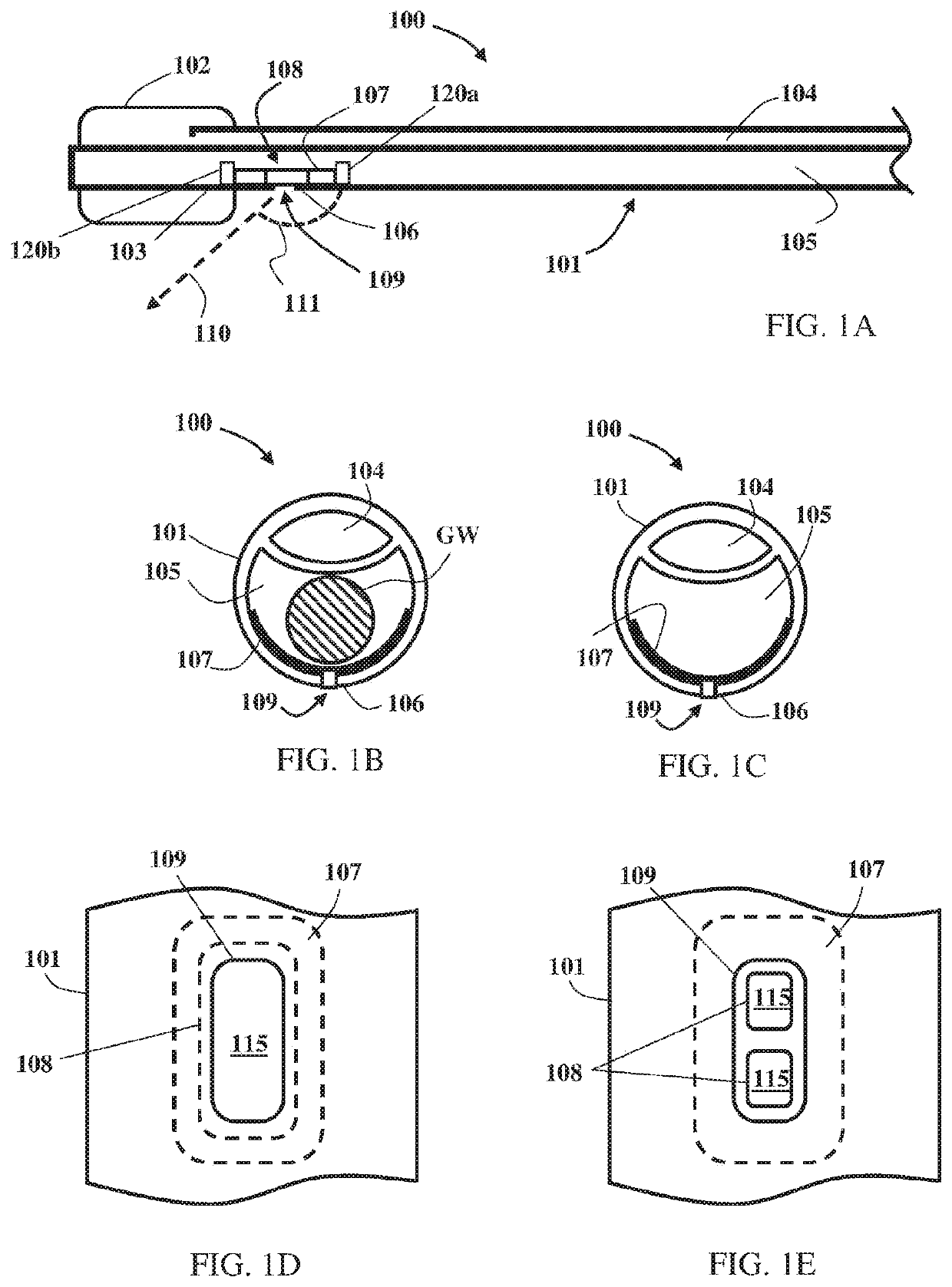
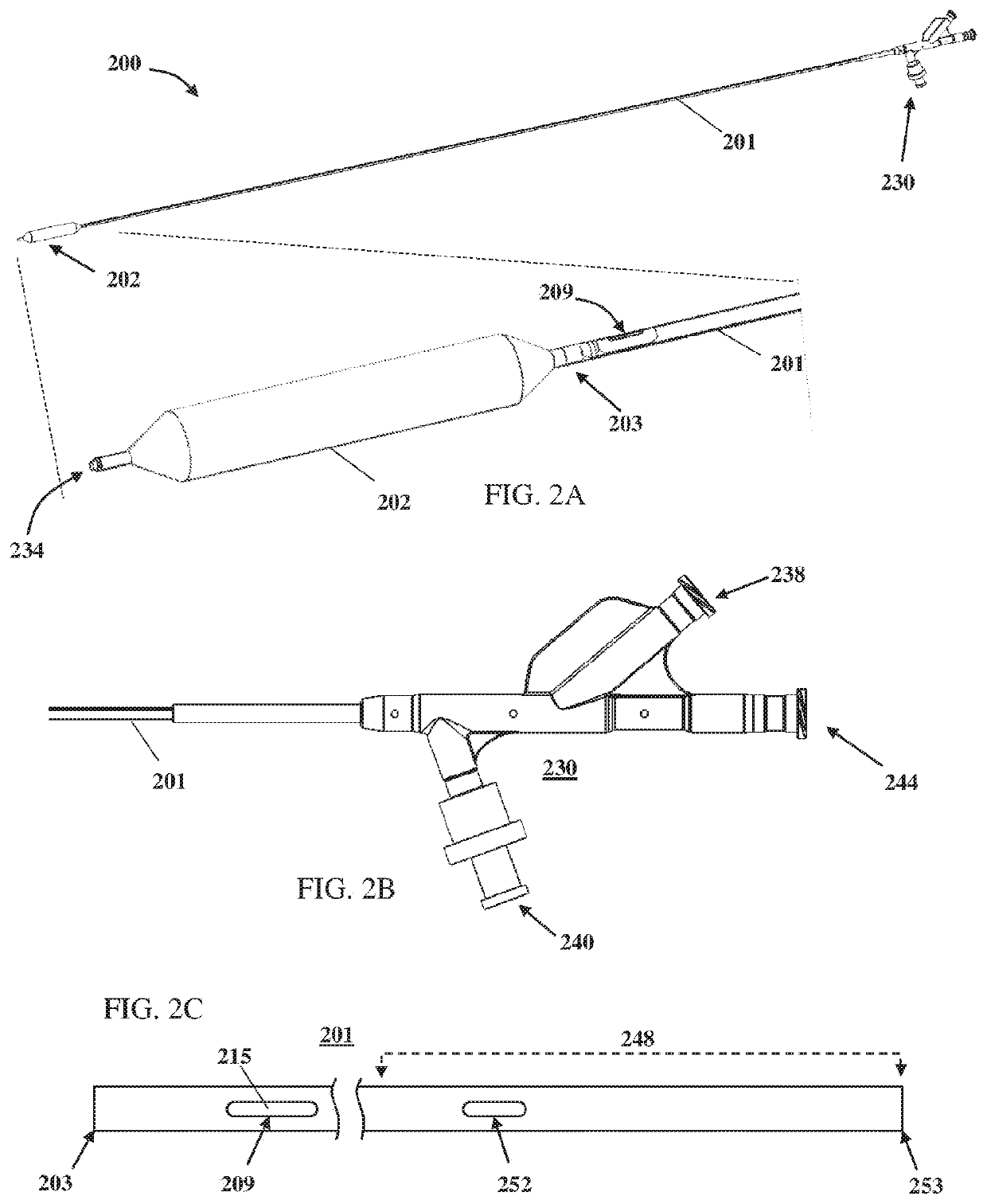
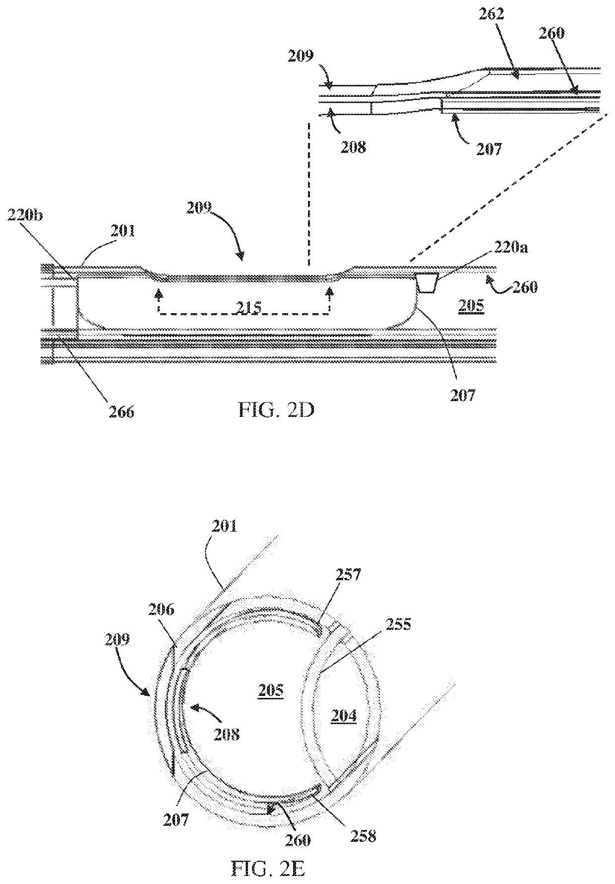
[0045]The present invention, in some embodiments thereof, relates to infusion balloon catheters, and more particularly, but not exclusively, to an infusion balloon catheter with fortified (strengthened) infusion outlet port, and a method of manufacturing thereof. Some of these or other embodiments, particularly relate to infusion balloon catheters possessing a sufficiently enlarged infusion outlet port for diminishing resistance to flow. Some of these or other embodiments particularly relate to balloon infusion catheters having their infusion outlet port positioned proximally to the balloon member they carry. Some embodiments of the invention are particularly suitable for use in applications of, or relating to, dialysis procedures that involve injecting imaging contrast material into the blood stream of a subject.

[0046]By implementing a substantially enlarged opening proximally and in approximation to the balloon member, the catheter shaft section encompassing this opening will suff...


PUM

PropertyMeasurementUnit
thicknessaaaaaaaaaa
lengthaaaaaaaaaa
obtuse angleaaaaaaaaaa

Abstract

Infusion balloon catheter with fortified proximal infusion outlet port, and manufacturing thereof. Infusion balloon catheter includes: inflatable balloon member; shaft having distal end attached to balloon member, and shaft wall enclosing: first lumen providing passage to balloon inflation fluid, and second lumen providing passage to infusion fluid and guidewire; and bending-resistant insert member housed in second lumen and located proximally to balloon member, insert member is affixed to, and conforms to shape of, shaft inner wall surface, and includes one or more openings(s). Shaft wall has infusion outlet port located along, and providing opening to, second lumen proximally to balloon member. Insert opening(s) is / are in direct fluid communication with infusion outlet port whose cross-sectional area is larger than that of infusion inlet opening. Bending-resistant insert member provides fortifying structural support to shaft wall portion surrounding infusion outlet port. Applicable to medical procedures involving injection of imaging contrast material or / and drugs.

Description

RELATED APPLICATION[0001]This application is a U.S. National Stage Entry Under 35 U.S.C. 371 of International Application No. PCT / IB2016 / 053804 filed on Jun. 26, 2016, which claims the benefit of priority under 35 USC 119(e) of U.S. Provisional Patent Application No. 62 / 184,536, filed Jun. 25, 2015, entitled “BALLOON CATHETER WITH FORTIFIED PROXIMAL INFUSION OUTLET PORT”. The contents of the above applications are incorporated herein by reference in their entireties.FIELD OF THE INVENTION[0002]The present invention, in some embodiments thereof, relates to infusion balloon catheters, and more particularly, but not exclusively, to an infusion balloon catheter with fortified (strengthened) proximal infusion outlet port, and a method of manufacturing thereof. Some embodiments of the invention are particularly suitable for use in applications of, or relating to, dialysis procedures that involve injecting imaging contrast material into the blood stream of a subject.BACKGROUND OF THE INVEN...

Claims


Application Information

Patent Timeline
Patent Type & Authority Patents(United States)
IPC IPC(8): A61M25/10A61L29/02A61M25/00A61M5/00A61L29/04
CPCA61M25/0052A61M25/1036A61M25/0026A61M25/10A61L29/04A61M25/007A61M5/007A61L29/02A61M25/0029A61M2025/105A61M2025/1061A61M2025/1084A61M2025/0039A61M25/0028A61M2025/0037A61M2025/0073A61M2025/1052
Inventor TAL, MICHAEL GABRIELBERNSTEIN, GILSANDACH, LIMOR
Owner A V MEDICAL TECH
Why Eureka
Try Eureka