Thin film resistor

a thin film resistor and resistor technology, applied in resistors, resistive materials, basic electric elements, etc., can solve the problem of slightly marred resistivity of conventional thin film resistors, and achieve the effect of reducing tcr and increasing resistivity

Active Publication Date: 2020-04-14
LEE YING CHIEH
View PDF0 Cites 0 Cited by
  • Summary
  • Abstract
  • Description
  • Claims
  • Application Information

AI Technical Summary

Benefits of technology

[0008]In an example, sum of atomic percentages of Ni and Ta is larger than 45 at %. Alternatively, sum of atomic percentages of Y and Ta is larger than 30 at %. As such, the thin film resistor can have not only enhanced resistivity, but also decreased TCR near zero.

Problems solved by technology

However, a resistivity of the conventional thin film resistor is slightly marred.

Method used


Image

  • Thin film resistor

Examples


Embodiment Construction

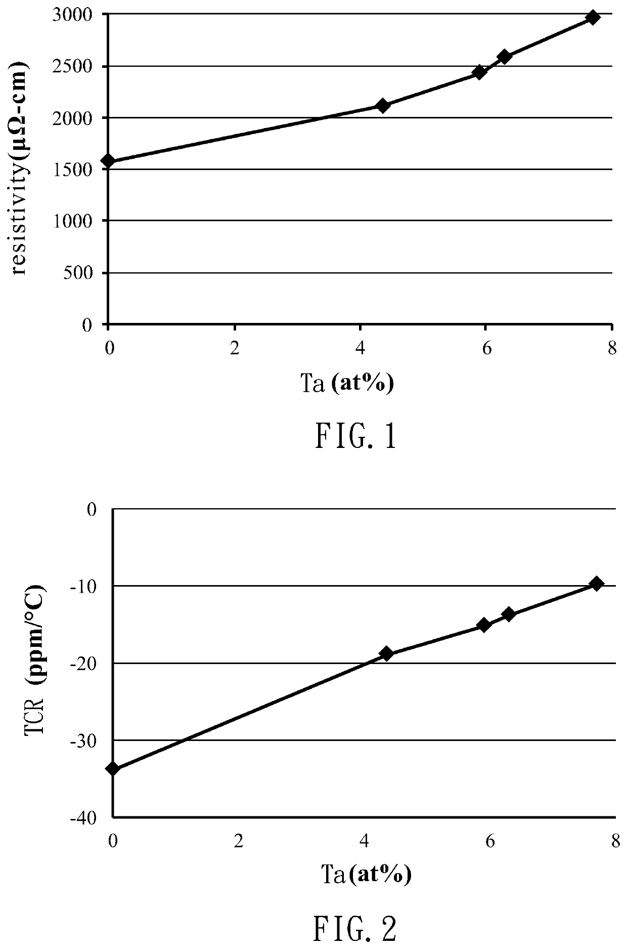
[0013]A thin film resistor according to an embodiment of the present invention can include nickel (Ni), chromium (Cr), manganese (Mn), yttrium (Y) and tantalum (Ta). As an example, the thin film resistor can include 30-45 at % of Ni, 15-30 at % of Cr, 1-10 at % of Mn, 10-30 at % of Y and 1-20 at % of Ta. Preferably, the thin film resistor includes 42.9-43.8 at % of Ni, 19.9-20.7 at % of Cr, 4.7-5.6 at % of Mn, 24.8-25.6 at % of Y and 4.3-7.7 at % of Ta. Moreover, the sum of atomic percentages of Ni and Ta is larger than 45 at %. Alternatively, the sum of atomic percentages of Y and Ta is larger than 30 at %. With such performance, the thin film resistor has not only the increased resistivity, but also the temperature coefficient of resistance (TCR) near zero.

[0014]The thin film resistor can be produced by any conventional method for producing thin film resistors, such as vacuum evaporation or sputtering. In this embodiment, D.C. magnetron sputtering is used, metal meeting the compos...


PUM

PropertyMeasurementUnit
thicknessaaaaaaaaaa
resistanceaaaaaaaaaa
temperature coefficient of resistanceaaaaaaaaaa

Abstract

A thin film resistor has a higher resistivity compared to that of a conventional thin film resistor. The thin film resistor includes 30-45 at % of nickel, 15-30 at % of chromium, 1-10 at % of manganese, 10-30 at % of yttrium and 1-20 at % of tantalum.

Description

CROSS REFERENCE TO RELATED APPLICATIONS[0001]The application claims the benefit of Taiwan application serial No. 107102222, filed Jan. 22, 2018, the entire contents of which are incorporated herein by reference.BACKGROUND OF THE INVENTION1. Field of the Invention[0002]The present invention generally relates to a resistor and, more particularly, to a thin film resistor.2. Description of the Related Art[0003]Resistors are a type of passive components and can be classified into two types, one of which is a thick film resistor, and the other one is a thin film resistor. Thick film resistor is generally used in consumer electronics having lower requirements in the accuracy and tolerance of resistance. Thin film resistor has relatively high accuracy along with improvement in the preparation methods and materials and can, thus, be used in delicate instruments, such as medical instruments, industrial computers, and automobiles, thereby having a high economic potential.[0004]The ingredients ...

Claims


Application Information

Patent Timeline
Patent Type & Authority Patents(United States)
IPC IPC(8): C22C19/05C22C30/00H01C7/00
CPCC22C30/00C22C19/05H01C7/006C22C19/058H01C7/06H01C17/08H01C17/12
Inventor LEE, YING-CHIEH
Owner LEE YING CHIEH
Why Eureka
Try Eureka