Light-emitting device

a technology of light-emitting devices and sealing resins, which is applied in the direction of semiconductor devices, basic electric elements, electrical equipment, etc., can solve the problems of large variations, color unevenness on the light-emitting surface of the light-emitting device, and so as to reduce the life span of the sealing resin and the light-emitting efficiency of the led element, the effect of easy discharg

Active Publication Date: 2020-04-21
CITIZEN ELECTRONICS CO LTD +1
View PDF15 Cites 0 Cited by
  • Summary
  • Abstract
  • Description
  • Claims
  • Application Information

AI Technical Summary

Benefits of technology

[0004]The phosphor in the sealing resin generates heat when excited by light from the LED element. Thus, the phosphor dispersed in the sealing resin raises the temperature of the sealing resin when the device emits light, which reduces the life span of the sealing resin and the light-emitting efficiency of the LED element. Therefore, during the manufacture of the light-emitting device, it is desirable to cure the sealing resin after the phosphor is naturally deposited in the sealing resin, and thereby to arrange the phosphor close to the mount board of the LED element, so that the heat from the phosphor can be easily discharged toward the mount board.
[0007]It is an object of the present invention to provide a light-emitting device which can be manufactured without lowering yields, can easily discharge heat generated by a phosphor for converting the wavelength of light from an LED element, through a mount board, and hardly has angle directivity in chromaticity of the emitted light.

Problems solved by technology

Thus, the phosphor dispersed in the sealing resin raises the temperature of the sealing resin when the device emits light, which reduces the life span of the sealing resin and the light-emitting efficiency of the LED element.
However, if the phosphor is completely deposited in the sealing resin, the phosphor layer is unlikely to cover areas beside and obliquely above (i.e., areas around the upper surface of) the LED element, although the phosphor is accumulated on the upper surfaces of the mount board and LED element.
In this case, since light emitted obliquely upward from the LED element is subjected to insufficient wavelength conversion of the phosphor, the color corresponding to the emission wavelength of the LED element is conspicuous obliquely above the LED element, which leads to color unevenness on the light-emitting surface of the light-emitting device (in other words, the emitted light has angle directivity in chromaticity).
However, making the phosphor sink for only a short time to realize the intermediate state causes large variations between products, and hinders constantly manufacturing products having the same characteristics.
Thus, curing the sealing resin in the middle of sinking of the phosphor is not a realistic way.

Method used


Image

  • Light-emitting device
  • Light-emitting device
  • Light-emitting device

Examples


Embodiment Construction

[0015]Hereinafter, with reference to the accompanying drawings, a light-emitting device will be explained in detail. However, it should be noted that the present invention is not limited to the drawings or the embodiments described below.

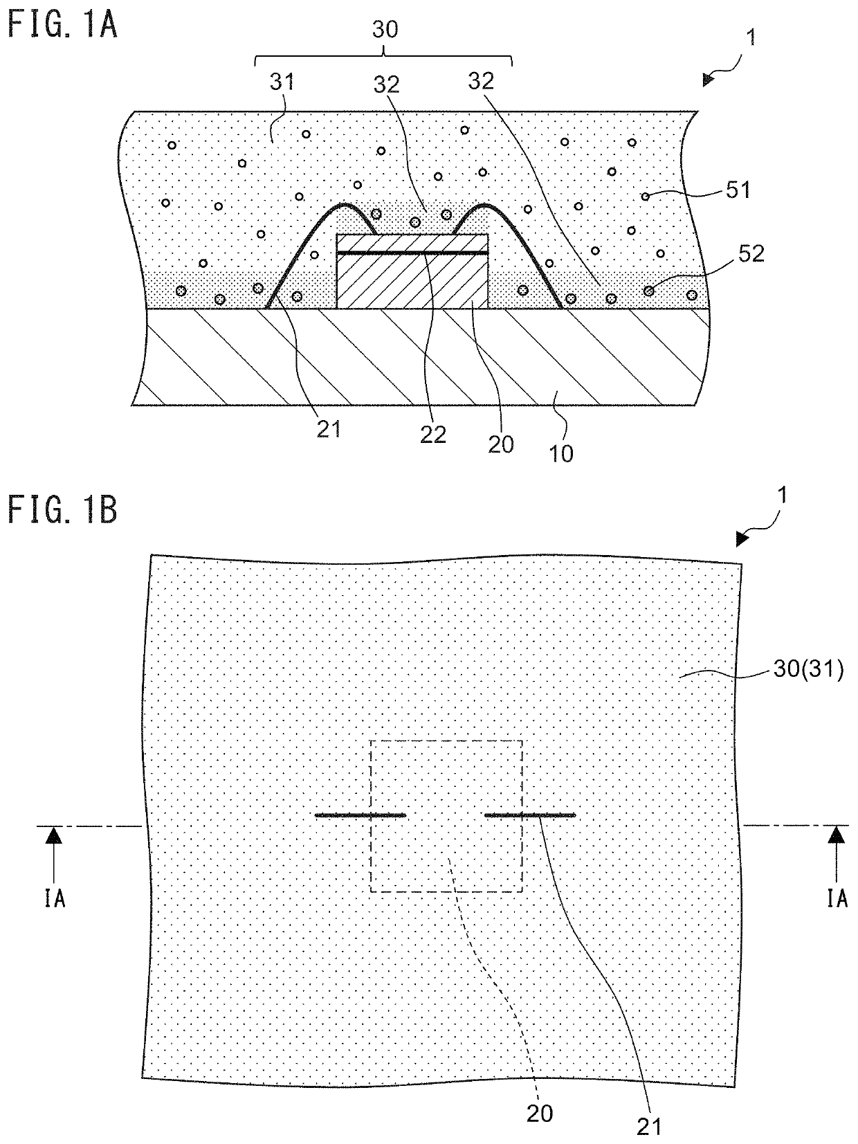
[0016]FIGS. 1A and 1B are a cross-sectional view and a top view of a light-emitting device 1, respectively. FIG. 1A shows a cross section of the light-emitting device 1 taken along line IA-IA in FIG. 1B. The light-emitting device 1 is a device (LED package) which includes an LED element as a light-emitting element and utilizes wavelength conversion of a phosphor for emitting white light, and is used as an LED light source for various kinds of applications, such as lighting equipment, floodlighting and illumination. The light-emitting device 1 includes, as its major components, a mount board 10, an LED element 20 and a sealing resin 30. The number of LED elements 20 is not limited to one, and the light-emitting device 1 may be a Chip-On-Board (COB) l...


PUM

PropertyMeasurementUnit
particle sizeaaaaaaaaaa
wavelengthaaaaaaaaaa
grain-size distributionaaaaaaaaaa

Abstract

Provided is a light-emitting device including a mount board, an LED element mounted on the mount board, and a translucent or transparent sealing resin being filled onto the mount board to seal the LED element. The sealing resin contains first and second particulate phosphors excited by emitted light from the LED element, and a nanoscale filler having an average particle size in the range of 1 nm to 100 nm. The specific gravity of the first particulate phosphor is smaller than that of the second particulate phosphor. The sealing resin includes a dispersion layer of the first particulate phosphor covering areas obliquely above and beside the LED element, and a deposition layer of the second particulate phosphor on upper surfaces of the mount board and the LED element. The first particulate phosphor is dispersed in the dispersion layer among aggregates formed by particles of the nanoscale filler.

Description

CROSS REFERENCE TO RELATED APPLICATION[0001]This application claims the benefit of Japanese Patent Application JP2017-158694, filed on Aug. 21, 2017. The disclosure of JP2017-158694 is herein incorporated by reference.TECHNICAL FIELD OF THE INVENTION[0002]The present invention relates to a light-emitting device.BACKGROUND OF THE INVENTION[0003]Light-emitting devices (LED packages) are known in which a light-emitting diode (LED) device is mounted on a substrate and sealed with a translucent sealing resin containing a phosphor. In such a light-emitting device, light emitted from the LED element is mixed with light generated by exciting the phosphor with the emitted light, thereby producing light of a desired color, such as white, according to the purpose.SUMMARY OF THE INVENTION[0004]The phosphor in the sealing resin generates heat when excited by light from the LED element. Thus, the phosphor dispersed in the sealing resin raises the temperature of the sealing resin when the device e...

Claims


Application Information

Patent Timeline
Patent Type & Authority Patents(United States)
IPC IPC(8): H01L33/50H01L33/62H01L33/56H01L33/32
CPCH01L33/508H01L33/504H01L33/56H01L33/62H01L33/507H01L2933/0041H01L2933/0091H01L33/32
Inventor OYAMADA, NODOKA
Owner CITIZEN ELECTRONICS CO LTD
Why Eureka
Try Eureka