
Programmable automobile light bar

a technology of light bars and automobiles, applied in the field of light bars, can solve the problems of no known light bars and many disadvantages

Active Publication Date: 2020-04-28
PUTCO
View PDF11 Cites 4 Cited by
  • Summary
  • Abstract
  • Description
  • Claims
  • Application Information

AI Technical Summary

Benefits of technology

This patent is about a new light bar that can be used in a wide variety of applications and vehicles. The light bar has LEDs of different colors and can perform several functions, including emitting light in different patterns and strobing light. It has a solid state design with more than two thousand LEDs and is compact. The light bar also has a liquid-crystal display LCD, which can have independently controllable portions. The technical effects of this patent are improved performance and versatility of the light bar for various applications and vehicles.

Problems solved by technology

While conventional light bars provide many advantages, they suffer from many disadvantages not solved by the prior art.
No known light bars include the option to manually set a lighting pattern while simultaneously interpreting signals directly received from the electrical system of the vehicle.
Furthermore, there are no known light bars which reconcile whether a manual instruction from an operator of the vehicle or an automatic system for interpreting signals directly received from the electrical system of the vehicle should have priority over the other during simultaneous use.

Method used


Image

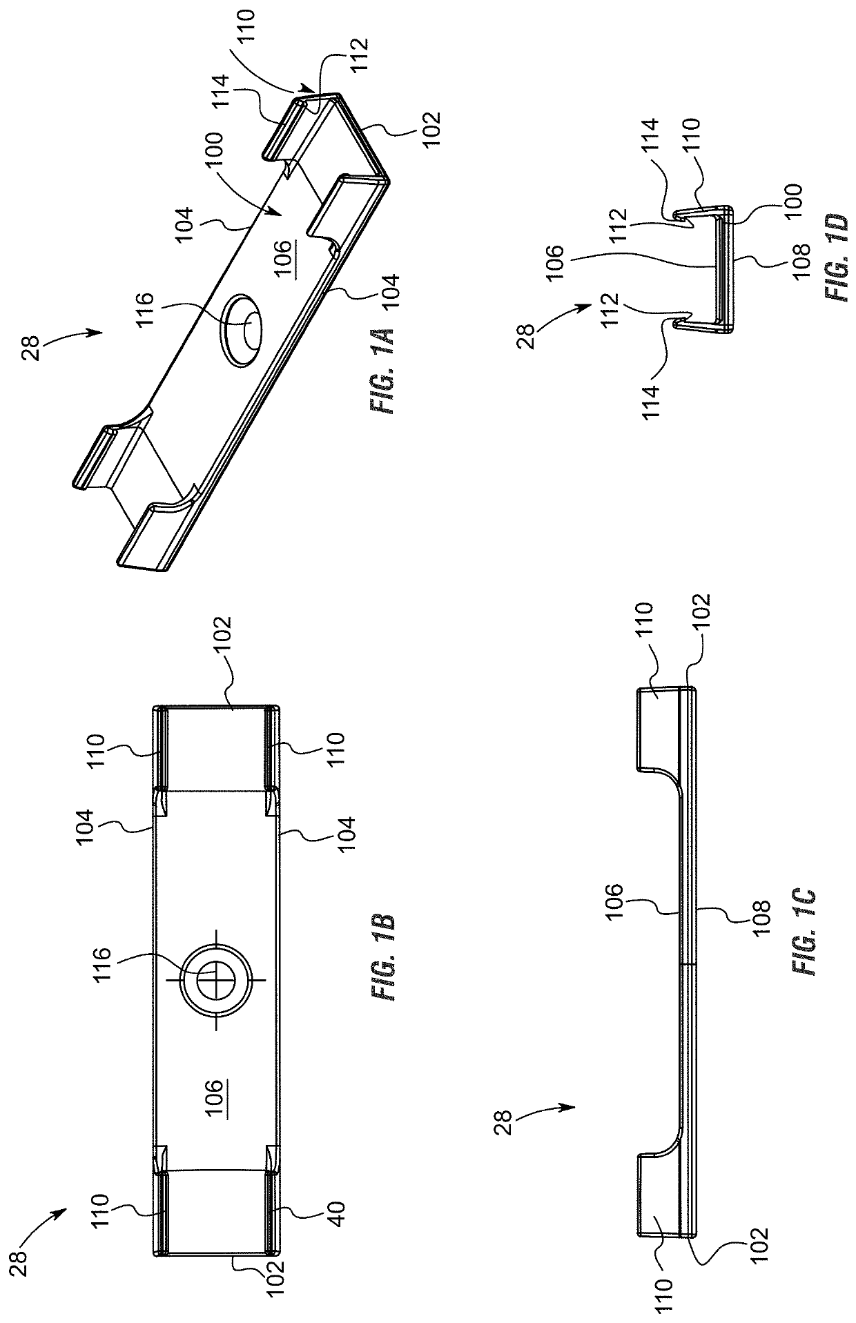
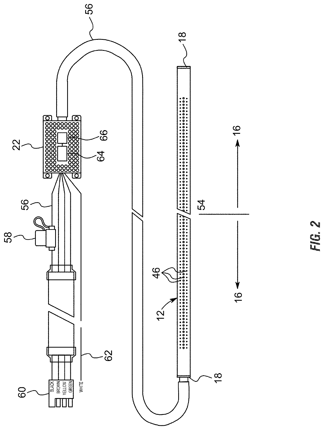
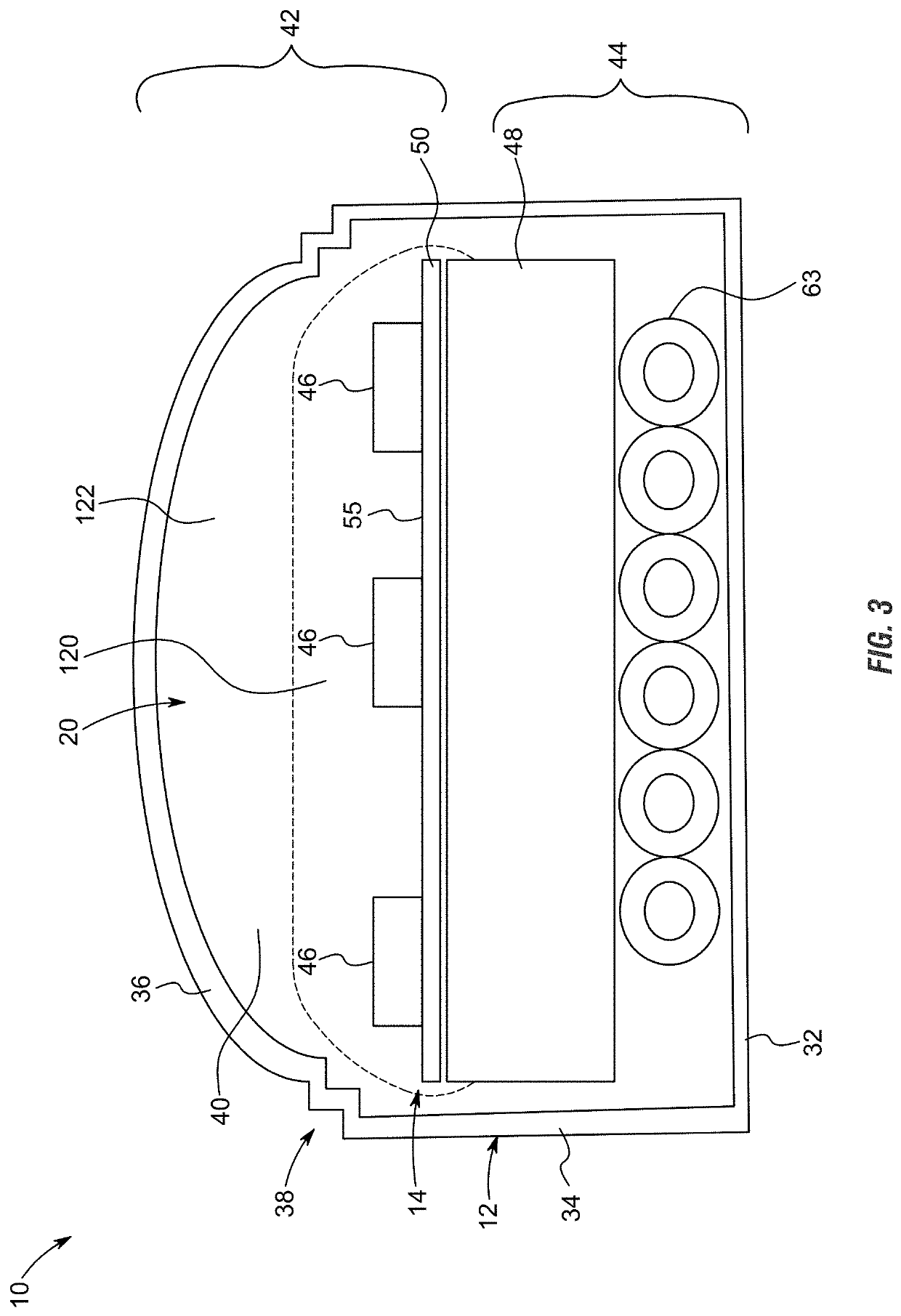
  • Programmable automobile light bar
  • Programmable automobile light bar
  • Programmable automobile light bar

Examples


Embodiment Construction

Definitions—Introductory Matters

[0067]The following definitions and introductory matters are provided to facilitate an understanding of the present invention. Unless defined otherwise, all technical and scientific terms used herein have the same meaning as commonly understood by one of ordinary skill in the art to which embodiments of the present invention pertain.

[0068]The terms “a,”“an,” and “the” include singular and plural referents.

[0069]The term “or” is synonymous with “and / or” and means any one member or combination of members of a particular list.

[0070]The terms “invention” or “present invention” as used herein are not intended to refer to any single embodiment of the particular invention but encompass all possible embodiments as described in the specification and the claims.

[0071]The term “about” as used herein refers to slight variations in numerical quantities with respect to any quantifiable variable. One of ordinary skill in the art will recognize inadvertent error can ...


PUM

PropertyMeasurementUnit
standby currentaaaaaaaaaa
currentaaaaaaaaaa
temperaturesaaaaaaaaaa

Abstract

A light bar has a circuit board positioned within a housing and having a plurality of light emitting diodes (LEDs) or a thin-film-transistor liquid-crystal display (TFT LCD) is configured to transmit light. The housing has wiring electrically connected to a controller. The controller is configured to receive signals from the electrical system of the vehicle, interpret the signals received from the electrical system of the vehicle, and in response automatically control illumination of independently controllable segments of the vehicle light bar. The controller is initially programmed to perform specific function(s) and / or strobe according to specific patterns and is thereafter at least partially restricted from being reprogrammed by a user to serve other function(s), either by restricting the emission of light in at least one color and / or preventing specific strobing pattern(s).

Description

CROSS REFERENCE TO RELATED APPLICATIONS[0001]This is a continuation-in-part patent application which claims priority under 35 U.S.C. § 120 to U.S. Ser. No. 16 / 176,112, filed Oct. 31, 2018, herein incorporated by reference in its entirety, including without limitation, the specification, claims, and abstract, as well as any figures, tables, appendices, or drawings thereof.FIELD OF THE INVENTION[0002]This invention relates to lights. More specifically, and without limitation, this invention relates to a light bar which is particularly well suited for use on trucks in a low-profile manner in the space above a bumper and below the tailgate.BACKGROUND OF THE INVENTION[0003]The background description provided herein gives context for the present disclosure. Work of the presently named inventors, as well as aspects of the description that may not otherwise qualify as prior art at the time of filing, are neither expressly nor impliedly admitted as prior art.[0004]Vehicle lights are old and ...

Claims


Application Information

Patent Timeline
Patent Type & Authority Patents(United States)
IPC IPC(8): B60Q1/26B60Q1/52B60Q1/44B60Q1/34B60Q1/00F21V14/00G02F1/137F21V23/00F21S43/14G02F1/1368F21W103/20F21W103/30F21W103/35F21W103/45F21W107/10F21Y113/17F21Y115/10
CPCF21V23/009B60Q1/0041B60Q1/52B60Q1/0076G02F1/137B60Q1/0035B60Q1/44B60Q1/34B60Q1/0088F21V14/003G02F1/1368F21S43/14F21W2103/20B60Q2400/20F21Y2115/10F21W2103/45F21W2107/10F21W2103/30F21Y2113/17F21W2103/35B60Q1/2611F21S41/645B60Q1/46B60Q1/22G02F1/1362G02F1/133603G02F1/133608G02F1/133322G02F1/133612B60Q2800/20
Inventor ELWELL, JAMES P.ELWELL, II, JAMES P.BURHITE, JOSHUA J.
Owner PUTCO
Learn More