Catheter having a distal section with spring sections for biased deflection

a catheter and distal tip technology, applied in the field of electrophysiological catheters, can solve the problems of reducing the accuracy of the position sensing capabilities of the sensor, limiting the flexibility and deflection of the distal tip section, and forming a lesion within the cardiac tissue which is electrically non-conductive, etc., to achieve the effect of reducing the axial loading capability, reducing the axial load, and ensuring the stability of the catheter

Active Publication Date: 2020-05-05
BIOSENSE WEBSTER (ISRAEL) LTD
View PDF123 Cites 1 Cited by
  • Summary
  • Abstract
  • Description
  • Claims
  • Application Information

AI Technical Summary

Benefits of technology

[0016]The present invention is directed to a catheter having a distal section with a spring member that allows for biased and more predictable deflection to enable better contact between tissue and electrodes carried on the distal section. The spring member has an elongated hollow structure on which ring electrodes are mounted at selected locations along the length of the structure. At least one section of the spring member extending between the ring electrodes has a predetermined cut pattern that includes at least one row of alternating slots and ribs along a first side of the structure and at least one longitudinal spine along a second side of the structure, where the first side is relatively more compressible and the second side is relatively less compressible, in providing the distal section with biased deflection within a plane defined by the two sides. Alternatively, where each section of the spring member has two rows of slots and ribs opposing each other along a first diameter and two longitudinal spines opposing each other along a second diameter, the distal section has a biased deflection in two opposing directions in a first plane defined by the first diameter while having limited, if any, deflection in a second plane defined by the second diameter. Where the first and second diameters are generally perpendicular, the spring member allows the distal section to have bi-directional deflection in the first plane while allowing limited, if any, deflection in the second plane to maintain torquability, axial loading capabilities, and side force performance.
[0019]The catheter includes a tip electrode having a shell wall that defines a cavity through which fluid flows and exits via fluid ports formed in the shell wall. The cavity is sealed by an internal member that extends into the cavity to safely house a position sensor for the tip electrode. A proximal portion of the internal member disperses fluid entering the tip electrode for a more uniform flow through the cavity. As such, fluid is fed to the more distal fluid ports in the tip electrode for more uniform cooling at all locations on the tip electrode.

Problems solved by technology

The tissue is heated sufficiently to cause cellular destruction in the cardiac tissue resulting in formation of a lesion within the cardiac tissue which is electrically non-conductive.
Because of the size of the tip electrode and the limited interior space therein, the EM sensor is often positioned outside of the tip electrode, proximally thereof, and often off-axis from the tip electrode which can reduce the accuracy of the position sensing capabilities of the sensor.
Being outside the tip electrode, the position sensor is also exposed to bending stresses and can limit the flexibility and deflection of the distal tip section.
Moreover, the sensor can be damaged by RF energy during ablation.
Where the distal tip is irrigated, the efficiency of irrigated cooling becomes a significant factor as ablation procedures can last five or six hours resulting in extensive fluid-loading in the patient.
As lumens are needed for other components, such as puller wires, lead wires, and / or irrigation tubing, it becomes difficult to maintain typical catheter sizes.
As catheters become more complex, more components are incorporated and thus the allocation of space for each component becomes more challenging.
However, if the portion is too stiff, it does not conform to the tissue and the electrodes cannot make solid contact for effective lesions.
If the region between the ring electrodes deflects too much during catheter deflection, the ring electrodes may be pulled away from the tissue also preventing the formation of effective lesions.

Method used


Image

  • Catheter having a distal section with spring sections for biased deflection
  • Catheter having a distal section with spring sections for biased deflection
  • Catheter having a distal section with spring sections for biased deflection

Examples


Embodiment Construction

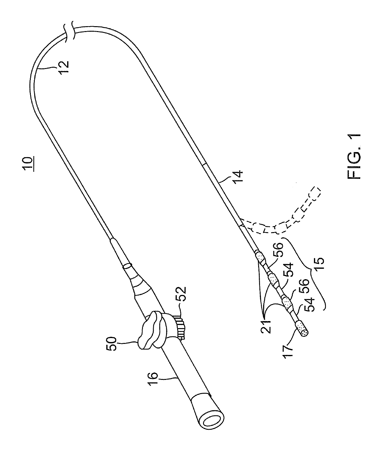
[0042]FIG. 1 illustrates an embodiment of a catheter 10 carrying irrigated tip and ring electrodes with improved deflection characteristics. The catheter has an elongated catheter body 12 with proximal and distal ends, an intermediate deflectable section 14 at the distal end of the catheter body 12, and a distal section 15 which carries an irrigated tip electrode 17 and a plurality of irrigated ring electrodes 21. The catheter also includes a control handle 16 at the proximal end of the catheter body 12 for controlling deflection of at least the intermediate section 14. Advantageously, the distal section 15 has a spring member that enables a more controlled and biased deflection, including uni- or bi-directional deflection within a single plane. Along its length, the spring member houses discrete support members, each of which supports a respective ring electrode while allowing the spring member as a whole to deflect more predictably in enabling better contact between the tissue and...


PUM

PropertyMeasurementUnit
temperatureaaaaaaaaaa
inner diameteraaaaaaaaaa

Abstract

A catheter has a distal section that includes a spring member having at least a slot, a rib and a spine for biasing the distal section for deflection within a single plane. Depending on the plurality and orientation of slot(s), rib(s) and spine(s)s, the distal section can allow for deflection in two opposing directions while allowing only limited deflection in perpendicular directions to maintain torquability, axial loading capabilities, and side force performance.

Description

FIELD OF INVENTION[0001]The present invention relates to an electrophysiologic catheter that is particularly useful for ablation and sensing electrical activity of heart tissue.BACKGROUND OF INVENTION[0002]Electrode catheters have been in common use in medical practice for many years. Diagnosis and treatment of cardiac arrythmias by means of electrode catheters include mapping the electrical properties of heart tissue and selectively ablating cardiac tissue by application of energy. Such ablation can cease or modify the propagation of unwanted electrical signals from one portion of the heart to another. The ablation process destroys the unwanted electrical pathways by formation of non-conducting lesions. Various energy delivery modalities have been disclosed for forming lesions, and include use of microwave, laser and more commonly, radiofrequency energies to create conduction blocks along the cardiac tissue wall.[0003]In a two-step procedure—mapping followed by ablation—electrical ...

Claims


Application Information

Patent Timeline
Patent Type & Authority Patents(United States)
IPC IPC(8): A61B18/14A61M25/01A61B18/00A61B34/20A61M25/00
CPCA61M25/0138A61B18/1492A61B2218/002A61M25/0051A61B2018/00083A61M2025/0166A61B2018/00011A61M2025/0161A61B2018/00107A61B2018/00839A61B34/20A61B2018/00821A61B2018/00029A61B2017/00309
Inventor GARCIA, ARIELSCHULTZ, JEFFREY W.
Owner BIOSENSE WEBSTER (ISRAEL) LTD
Why Eureka
Try Eureka