
Driving device and liquid crystal display device

a technology of liquid crystal display panel and driving device, which is applied in the field of display, can solve the problems of non-uniform brightness of the display panel and adverse effects on the display effect of the display panel

Active Publication Date: 2020-05-05
TCL CHINA STAR OPTOELECTRONICS TECH CO LTD +1
View PDF6 Cites 0 Cited by
  • Summary
  • Abstract
  • Description
  • Claims
  • Application Information

AI Technical Summary

Benefits of technology

The present invention provides a control circuit for a liquid crystal display panel that improves the uniform brightness and display effect of the image displayed. By shortening the time period during which the positive polarity voltage is provided to the source line and prolonging the time period during which the negative polarity voltage is provided to the source line, the control circuit compensates for the charging efficiency difference between the positive and negative polarity voltages on the pixel. This results in a more uniform light output and improved display effect.

Problems solved by technology

As a result, an image displayed in the liquid crystal display panel would have a non-uniform brightness, and a display effect thereof would be adversely affected.

Method used


Image

  • Driving device and liquid crystal display device
  • Driving device and liquid crystal display device
  • Driving device and liquid crystal display device

Examples


Embodiment Construction

[0034]The present disclosure will be explained in details with reference to the embodiments and the accompanying drawings, whereby it can be fully understood how to solve the technical problem by the technical means according to the present disclosure and achieve the technical effects thereof, and thus the technical solution according to the present disclosure can be implemented. It should be noted that, as long as there is no structural conflict, all the technical features mentioned in all the embodiments may be combined together in any manner, and the technical solutions obtained in this manner all fall within the scope of the present disclosure.

[0035]In order to solve the technical problem of non-uniform brightness of the image displayed in the traditional liquid crystal display panel and the unsatisfactory display effect thereof, the embodiment of the present disclosure provides a driving device of a liquid crystal display panel.

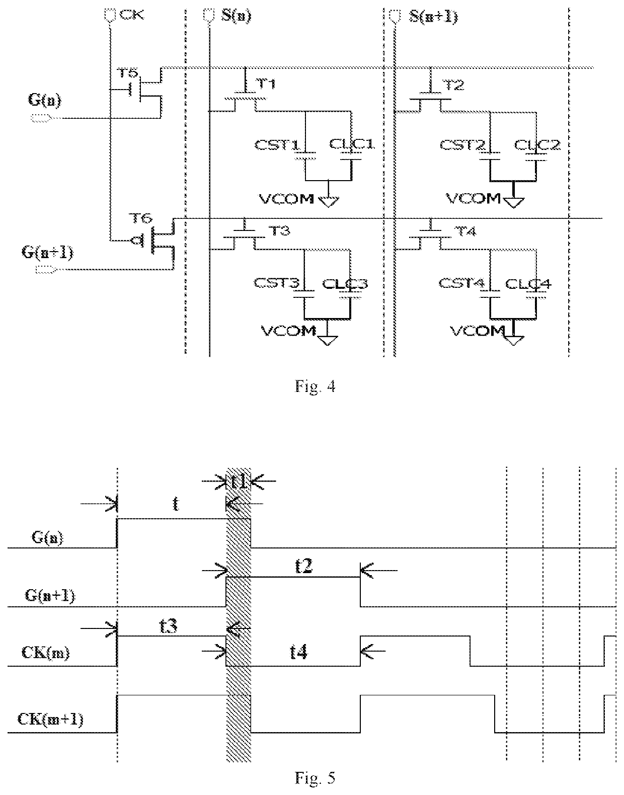
[0036]FIG. 4 schematically shows a driving device ...


PUM

PropertyMeasurementUnit
polarity voltageaaaaaaaaaa
timeaaaaaaaaaa
time thresholdaaaaaaaaaa

Abstract

A driving device and a liquid crystal display device are disclosed. In the driving device, a charging efficiency difference between a positive polarity voltage and a negative polarity voltage on a pixel can be compensated through increasing a duration of a gate driving signal, shortening a time period during which the positive polarity voltage is provided to a source line, and prolonging a time period during which the negative polarity voltage is provided to the source line. In this manner, the technical problem of non-uniform brightness of an image displayed in a traditional liquid crystal display panel and unsatisfactory display effect thereof can be solved.

Description

CROSS REFERENCE TO RELATED APPLICATIONS[0001]The present application claims the priority of Chinese patent application CN201510572226.3, entitled “Driving Device and Liquid Crystal Display Device” and filed on Sep. 9, 2015, the entirety of which is incorporated herein by reference.FIELD OF THE INVENTION[0002]The present disclosure relates to the technical field of display, and particularly to a driving device of a liquid crystal display panel and a liquid crystal display device which comprises a liquid crystal display panel and a driving device.BACKGROUND OF THE INVENTION[0003]In a Thin Film Transistor Liquid Crystal Display (TFT-LCD), a gate driving signal is generally provided to a gate of each TFT of a pixel region through a gate driving device so as to control an on / off state of the gate. In order to prevent liquid crystal molecules from being polarized, the LCD should be driven by an alternating driving method. At present, the alternating driving method is mainly realized throu...

Claims


Application Information

Patent Timeline
Patent Type & Authority Patents(United States)
IPC IPC(8): G09G3/36
CPCG09G3/3614G09G3/3648G09G3/3677G09G2310/067G09G2320/0219G09G2310/08G09G2320/0233
Inventor ZUO, QINGCHENG
Owner TCL CHINA STAR OPTOELECTRONICS TECH CO LTD
Learn More