
Cortical bone pin

a cortical bone and pin technology, applied in the field of cortical bone pins, can solve the problems of high abnormal arrangement of the bone of the toe, affecting the healing effect of the bone, so as to reduce the brittleness

Active Publication Date: 2020-05-19
LIFENET HEALTH
View PDF42 Cites 2 Cited by
  • Summary
  • Abstract
  • Description
  • Claims
  • Application Information

AI Technical Summary

Benefits of technology

[0006]In one aspect of the invention, a pin has an elongated body of a substantially cylindrical shape. The pin may include a raised portion, or a plurality of raised portions, that may be formed of peaks and troughs. Such raised portions are referred to herein as “barb(s).” The barbs may extend around the entire circumference of the pin. In certain embodiments, however, the barbs are located on only a portion of the circumference of the pin. The remainder of the circumference of the pin may be flattened. In certain embodiments, voids are created along the circumference of the barbs to create spokes. The pin may include a protrusion (also referred to as a “shoulder”) extending outward from the pin. In some embodiments, the pin is made of cortical bone. In some embodiments, the cortical bone pin is treated to reduce brittleness.

Problems solved by technology

Certain deformities such as hammer toe result in the bones of a toe being arranged in a highly abnormal manner.
This method suffers from several drawbacks.
Another drawback is the insertion point is an open wound, thus raising the possibility of infection.
This method suffers from the several drawbacks.
First, the metal pin is not resorbable nor is it removable.
Another drawback is the pin may migrate into one of the phalanges (especially the proximal phalange).
This may cause instability and a failure to fuse.

Method used


Image

  • Cortical bone pin
  • Cortical bone pin
  • Cortical bone pin

Examples


Embodiment Construction

[0026]Reference will now be made in detail to the preferred embodiments of the present invention, examples of which are illustrated in the accompanying drawings.

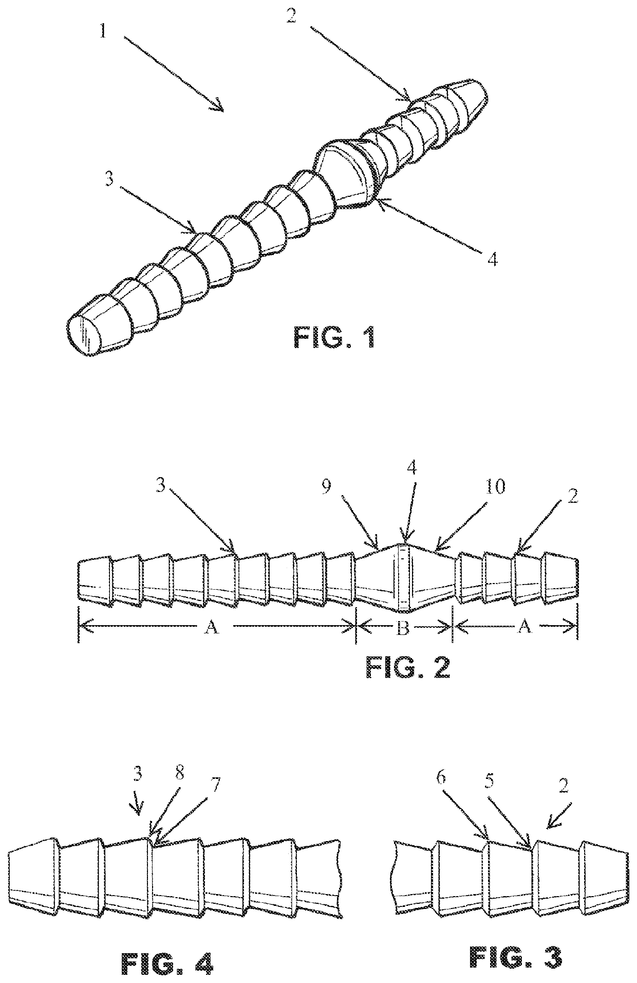
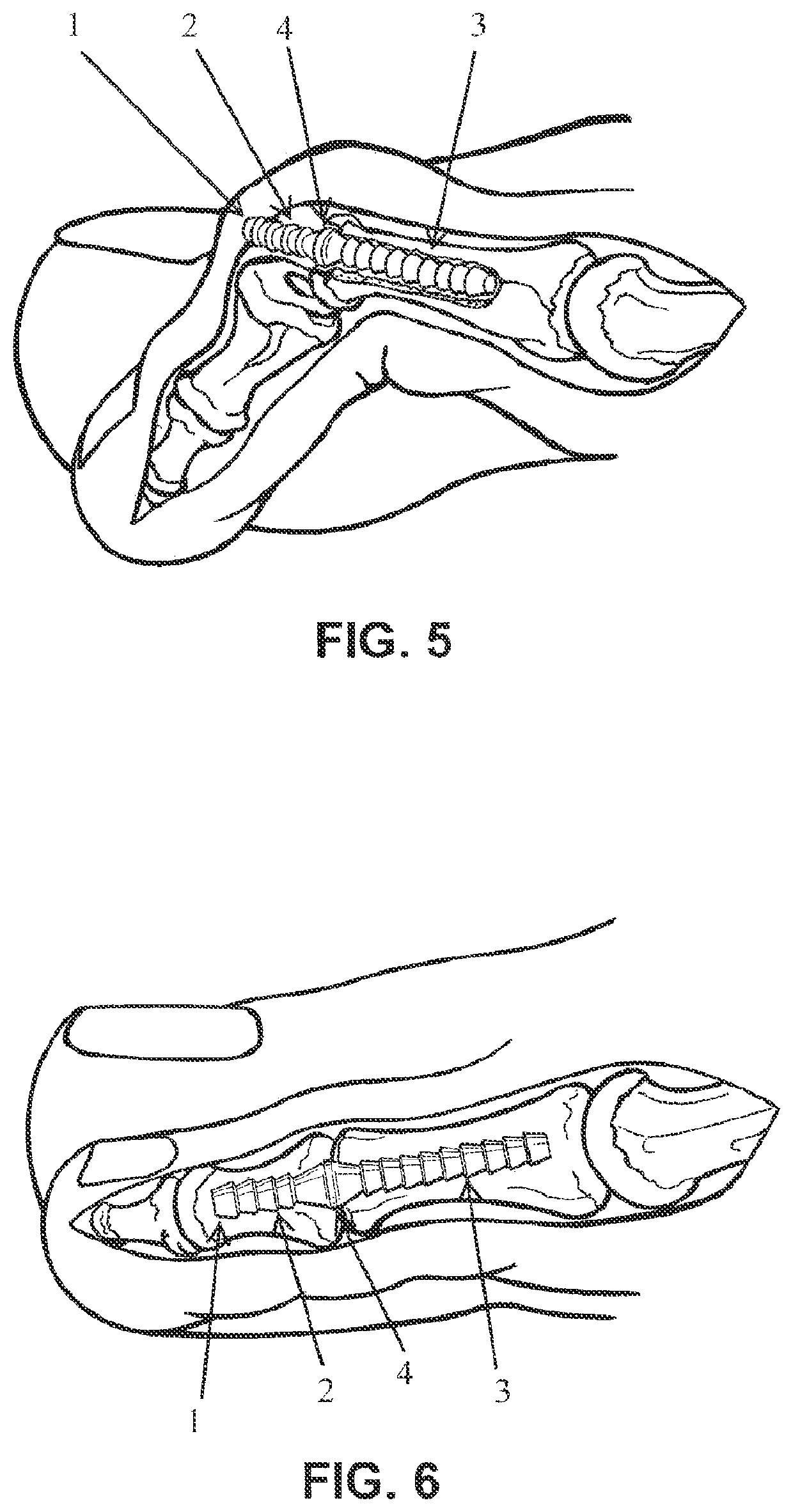
[0027]FIGS. 1-4 show a pin 1 according to a first exemplary embodiment of the present invention. As shown in FIG. 1, the pin 1 has a substantially cylindrical shape.

[0028]As shown in FIGS. 1-2, in one embodiment, barbs 2 are provided on the distal end of the pin. Barbs are preferred over threads as the torque required to install a threaded pin may stress the pin to failure. As shown in FIG. 3, the profile of the barbs 2 may be such that, as a barb 2 proceeds from a distal end to a proximal end, the barb 2 slopes gradually from a trough 5 to a crest 6, with an abrupt slope from a crest 6 to a trough 5. This way, the barbs 2 are designed to resist migration of the pin 1 toward a proximal direction after the pin has been inserted into the bone of a toe of a patient. Similarly, the barbs 2 are designed to resist migration of a d...


PUM


Abstract

A pin made of cortical bone may be inserted into adjoining bones of a toe to align and secure the bones. The pin may have barbs to prevent migration of the pin. The pin may include a shoulder to further prevent migration of the pin from the bones, to increase the strength of the pin, and to increase the surface area between the bone pin and the host bone. The pin may further include flattened portions on its circumference to aide in rotating the pin during insertion. The pin may be treated to reduce brittleness.

Description

[0001]This application claims the benefit of U.S. Provisional Application No. 61 / 650,364 filed May 22, 2012, which is hereby incorporated by reference.BACKGROUND OF THE INVENTIONField of the Invention[0002]The present invention relates to a pin for use in aligning and securing bones, and more particularly, to such a pin made of cortical bone that may be used for aligning and securing bones of a toe of a human patient. The present invention may also be used for aligning and securing bones of a hand, forefoot, or forearm of a patient. In particular, a fractured bone of a hand, foot, or forearm may be treated by inserting a pin according to the present invention into at least one segment of the fractured bone.Discussion of the Related Art[0003]Certain deformities such as hammer toe result in the bones of a toe being arranged in a highly abnormal manner. In some cases, the treatment for such deformities involves inserting a K-wire (Kirschner wire) through the tip of the toe and penetrat...

Claims


Application Information

Patent Timeline
Patent Type & Authority Patents(United States)
IPC IPC(8): A61B17/16A61B17/84A61B17/68A61B17/72
CPCA61B17/846A61B17/68A61B17/1686A61B17/7233A61B17/1682A61B17/7291A61F2/4225
Inventor CHEN, JINGSONGSANDER, THOMASPHELPS, DENNISPRITCHARD, ANDYBRACONE, ROBERTO
Owner LIFENET HEALTH
Learn More