
Method for fabricating a semiconductor structure on a semiconductor wafer

a technology of semiconductor wafers and structures, applied in the direction of semiconductor devices, electrical equipment, transistors, etc., can solve the problems of contamination problems of etching machines and affect and achieve the effect of improving the reliability or yield of processes

Active Publication Date: 2020-05-19
UNITED MICROELECTRONICS CORP +1
View PDF12 Cites 0 Cited by
  • Summary
  • Abstract
  • Description
  • Claims
  • Application Information

AI Technical Summary

Benefits of technology

[0005]One object of the present invention is to provide an improved method for fabricating a semiconductor structure on a semiconductor wafer, which can avoid formation of a metal silicide layer in the wafer bevel region of the silicon wafer during the metal silicidation process, thereby solving the contamination problem of the etching machine, and improving the reliability or yield of the process.
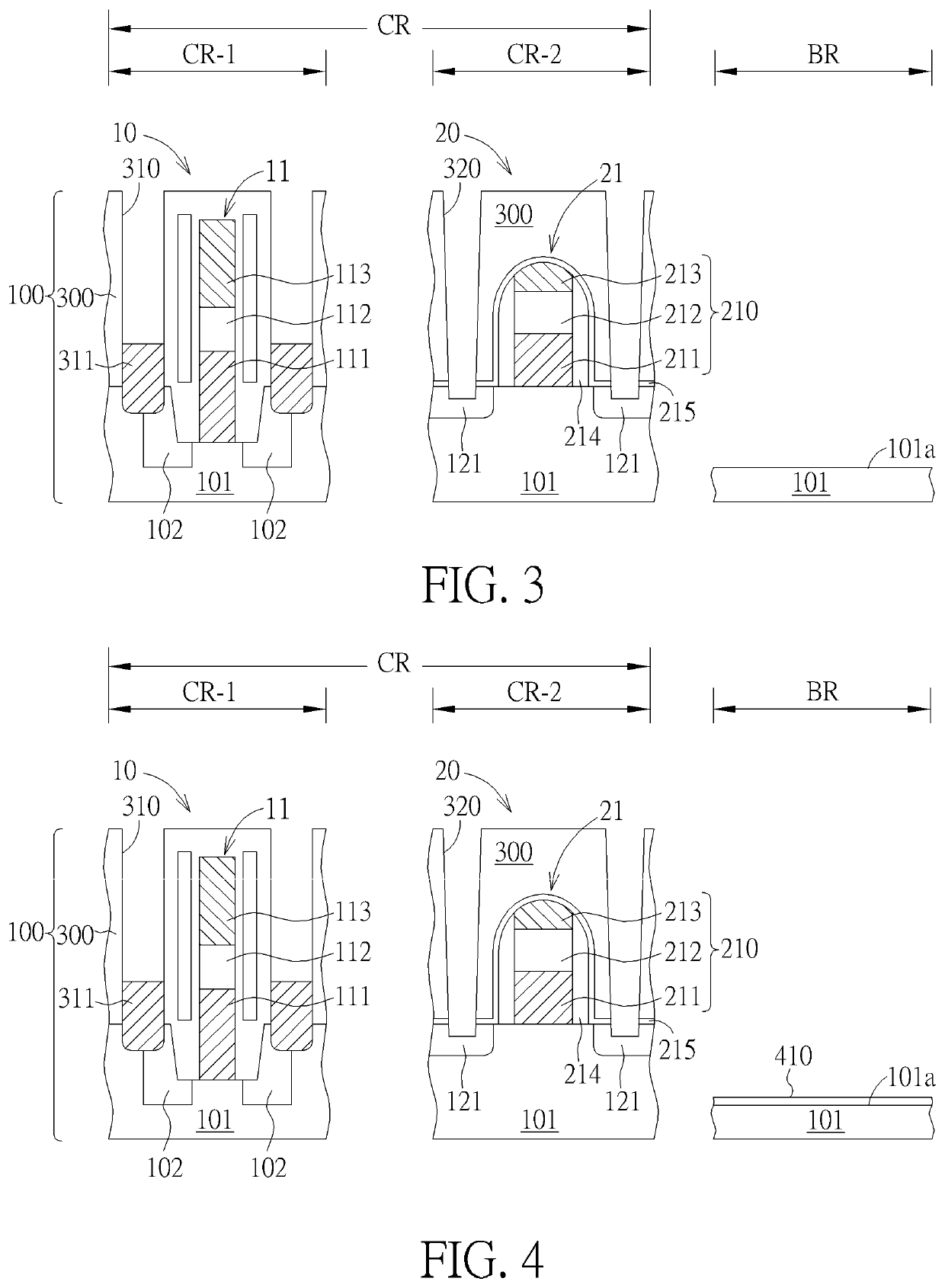
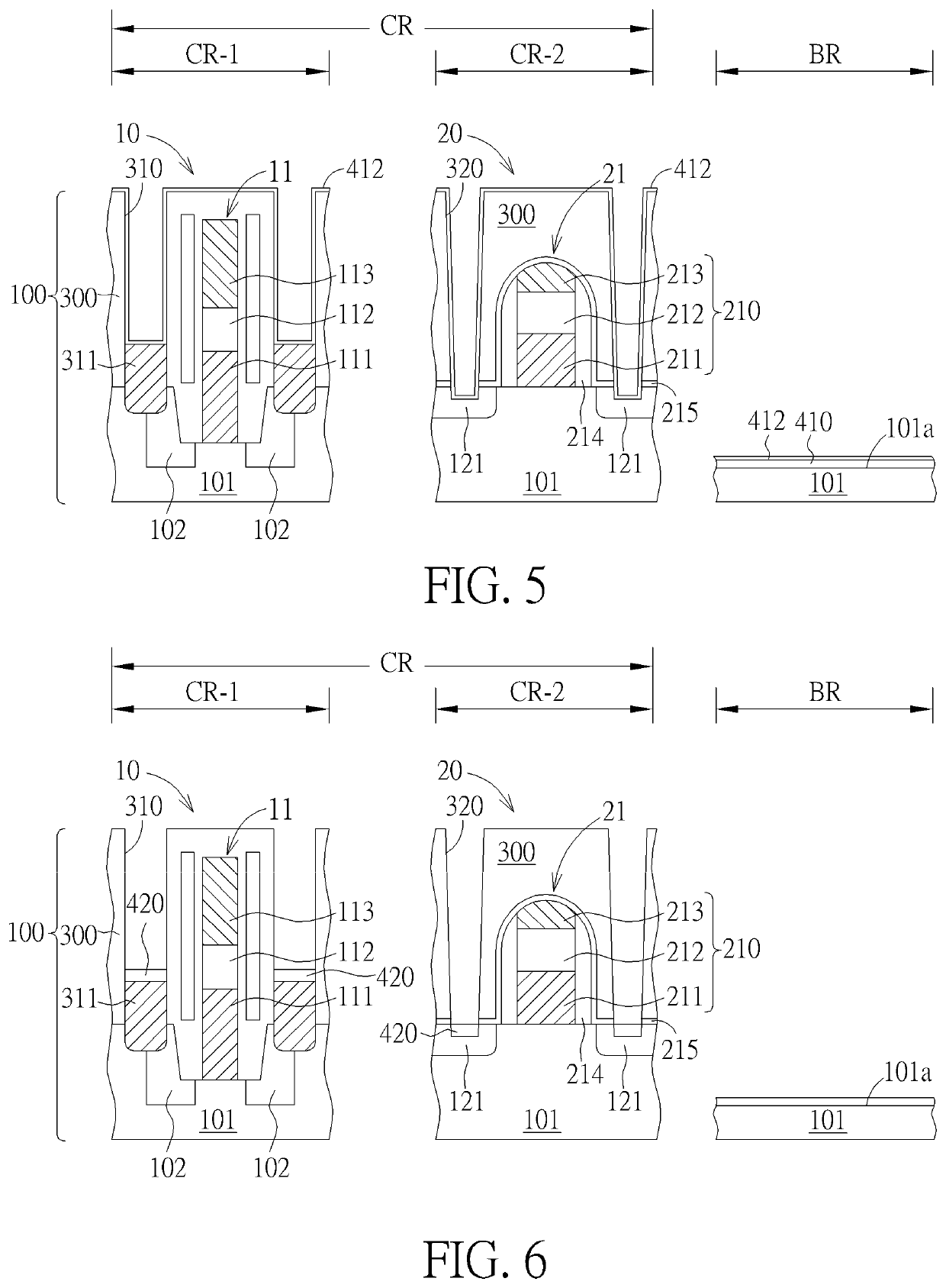
[0008]It is advantageous to use the present invention because by forming the blocking layer only in the wafer bevel region BR of the semiconductor wafer using the bevel plasma treatment before the metal silicidation process is performed, the formation of a metal silicide layer in the bevel region BR can be avoided during the metal silicidation process, and the contamination problem of the etching machine can be solved and the reliability or yield of the process is improved.

Problems solved by technology

The metal silicide layer formed in the wafer bevel region or the by-product formed in the subsequent etching process is likely to be peeled off within a chamber of an etching machine (for example, an etching chamber of the etching machine used to etch tungsten metal), which causes contamination problems of the etching machine and affects the reliability or yield of the process.

Method used


Image

  • Method for fabricating a semiconductor structure on a semiconductor wafer
  • Method for fabricating a semiconductor structure on a semiconductor wafer
  • Method for fabricating a semiconductor structure on a semiconductor wafer

Examples


Embodiment Construction

[0014]In the following detailed description of the invention, reference is made to the accompanying drawings which form a part hereof, and in which is shown, by way of illustration, specific embodiments in which the invention may be practiced. These embodiments are described in sufficient detail to enable those skilled in the art to practice the invention. Other embodiments may be utilized and structural, logical, and electrical changes may be made without departing from the scope of the present invention.

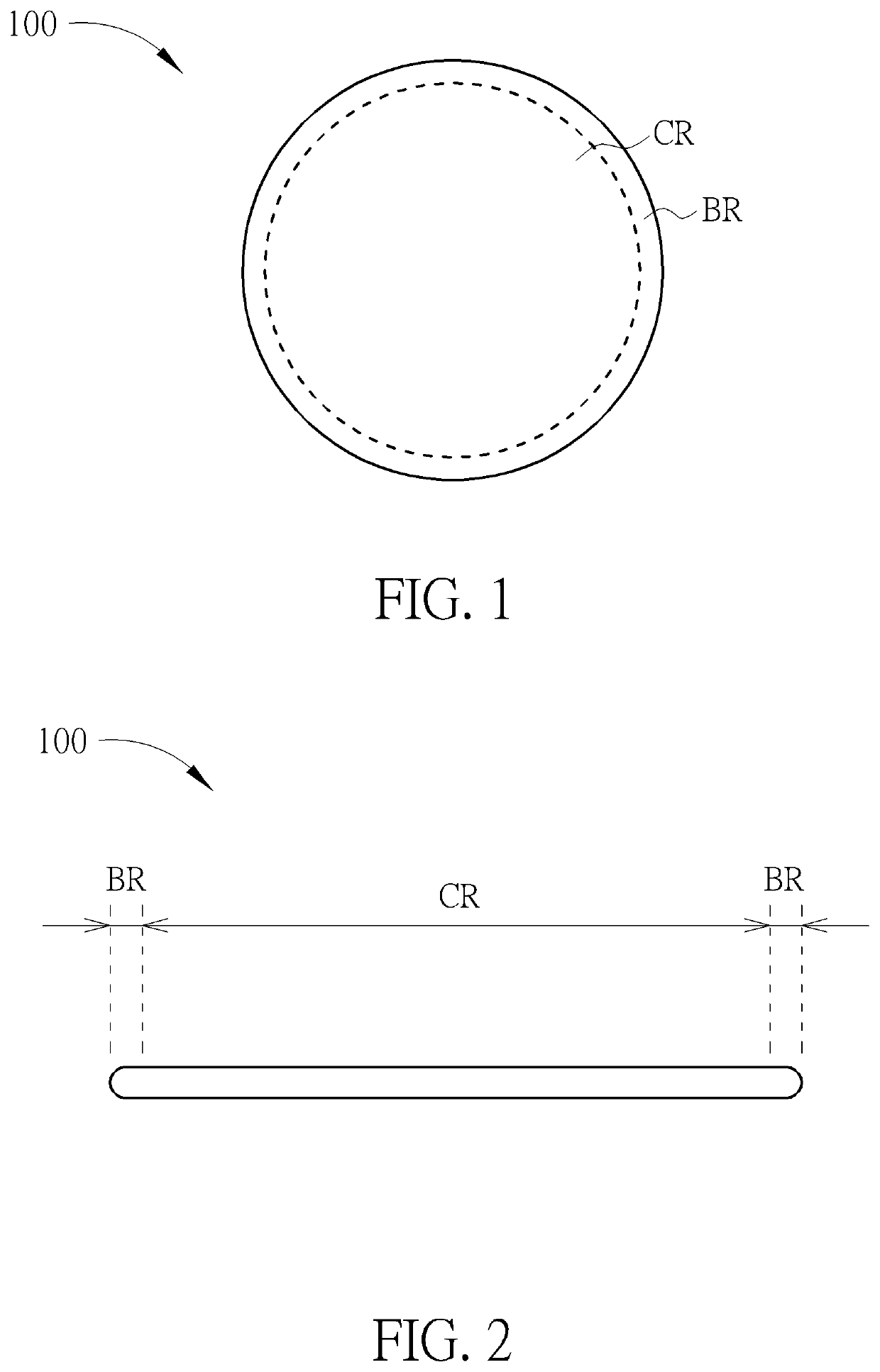
[0015]Please refer to FIG. 1 and FIG. 2. FIG. 1 illustrates a top view of a semiconductor wafer, and FIG. 2 is a cross-sectional view of the semiconductor wafer of FIG. 1. As shown in FIG. 1 and FIG. 2, the semiconductor wafer 100 has a disk-like structure having a central region CR and a wafer bevel region BR surrounding the central region CR. Taking a 12-inch wafer as an example, the wafer bevel region BR refers to an annular strip-shaped region having a width of about 1 mm to 3 ...


PUM

PropertyMeasurementUnit
widthaaaaaaaaaa
widthaaaaaaaaaa
thicknessaaaaaaaaaa

Abstract

A method for fabricating a semiconductor structure on a semiconductor wafer is disclosed. A semiconductor wafer having a first region, a second region, and a wafer bevel region is provided. The wafer bevel region has a silicon surface. A first semiconductor structure is formed in the first region and a second semiconductor structure is formed in the second region. The semiconductor wafer is subjected to a bevel plasma treatment to form a blocking layer only in the wafer bevel region. A silicidation process is then performed to form a silicide layer only in the first region and the second region.

Description

BACKGROUND OF THE INVENTION1. Field of the Invention[0001]The present invention relates to the field of semiconductor fabrication technology, and more particularly to a method of fabricating a semiconductor structure such as a storage node contact structure and / or a contact plug on a semiconductor wafer.2. Description of the Prior Art[0002]In semiconductor processes, especially in the front-end process, a so-called silicidation process is often required to reduce the contact resistance by forming a metal silicide layer on the silicon surface.[0003]However, according to the prior art method, a metal silicide layer is also formed in the wafer bevel region of the silicon wafer. The metal silicide layer formed in the wafer bevel region or the by-product formed in the subsequent etching process is likely to be peeled off within a chamber of an etching machine (for example, an etching chamber of the etching machine used to etch tungsten metal), which causes contamination problems of the e...

Claims


Application Information

Patent Timeline
Patent Type & Authority Patents(United States)
IPC IPC(8): H01L21/02H01L27/108H01L21/3065H01L21/67H01L21/3213
CPCH01L27/10897H01L21/02087H01L21/02252H01L21/3213H01L21/3065H01L21/67063H01L21/32053H10B69/00H01L21/02238H10B12/09H10B12/50
Inventor CHANG, FENG-YILEE, FU-CHECHEN, CHIEH-TEHSU, CHING-PIN
Owner UNITED MICROELECTRONICS CORP
Learn More