Temperature sensor, battery system and method for fitting a battery system

a temperature sensor and battery technology, applied in the field of lithium battery systems, can solve the problems of high cost, generally impossible, and inability to provide direct contact with the battery cell, and achieve the effects of simple and cost-effective, avoid short circuit, and favorable spring-elastic characteristics

Active Publication Date: 2020-05-19
ROBERT BOSCH GMBH
View PDF16 Cites 0 Cited by
  • Summary
  • Abstract
  • Description
  • Claims
  • Application Information

AI Technical Summary

Benefits of technology

[0008]The temperature sensor comprises at least one spring element having a preferably linear spring constant. It is preferred that the spring element is configured so as to retract or extend along a straight line. A spring force thus always acts in the same direction irrespective of the extent to which the spring element is compressed. The spring element is mechanically connected to the sensor head. This means that a spring force that is stored in the spring element is transmitted to the sensor head. Consequently, the sensor head may be pressed against the measuring site by means of the spring element and its spring force. It is preferred that the spring force is of such a magnitude that it is possible to avoid the contact between the sensor head and the measuring site becoming released, for example due to mechanical vibrations while a motor vehicle is traveling. It is possible to provide in accordance with the invention that the spring element and the connection wires are different components. In this case, it is preferred that the connection wires comprise at least one flexible or easily deformable part region in which the connection wires are configured for example in the form of a cable in order not to block a spring movement of the spring element nor to block a relative movability of the sensor head with respect to the battery management system.
[0031]It is preferred that one battery unit is provided that comprises multiple battery cells that are connected to one another in series and / or in parallel. It is preferred that the battery unit comprises a cell housing that surrounds the battery cells. The battery management system comprises a connection site for connecting or electrically coupling the connection wires of the at least one temperature sensor. The electrical coupling is preferably produced by means of a soldering procedure, welding procedure or a plugging-in procedure. The mechanical attachment is preferably produced by means of the electrical coupling. As the battery management system is being arranged on the battery unit, the spring element is compressed in such a manner that a preferably predefined or essentially predefined spring force is built up that presses the sensor head against the measuring site and consequently hinders or prevents the sensor head from lifting off the measuring site. It is preferred that the sensor head is attached to the measuring site via further means, such as for example by means of an adhesive. It is possible using the method in accordance with the invention to mount a battery system using simple means and in a cost-effective manner, wherein it is ensured that the sensor head is held against the measuring site. Moreover, the method in accordance with the invention has all the advantages that have already been described in connection with the battery system in accordance with the invention in accordance with the second aspect of the invention.

Problems solved by technology

In the case of known battery systems, the procedure of integrating temperature sensors, in particular when producing an electrical coupling by means of a plug-in system, often incurs high costs.
It is generally not possible in this case to provide a direct contact with the battery cell.
Furthermore, battery systems are becoming increasingly more complex and often comprise a comparatively small installation space for temperature sensors with the result that it is necessary to use especially configured temperature sensors rather than those of a standard design.
This likewise results in high production costs and also a high outlay with regard to the qualification expenses.

Method used


Image

  • Temperature sensor, battery system and method for fitting a battery system
  • Temperature sensor, battery system and method for fitting a battery system
  • Temperature sensor, battery system and method for fitting a battery system

Examples


first embodiment

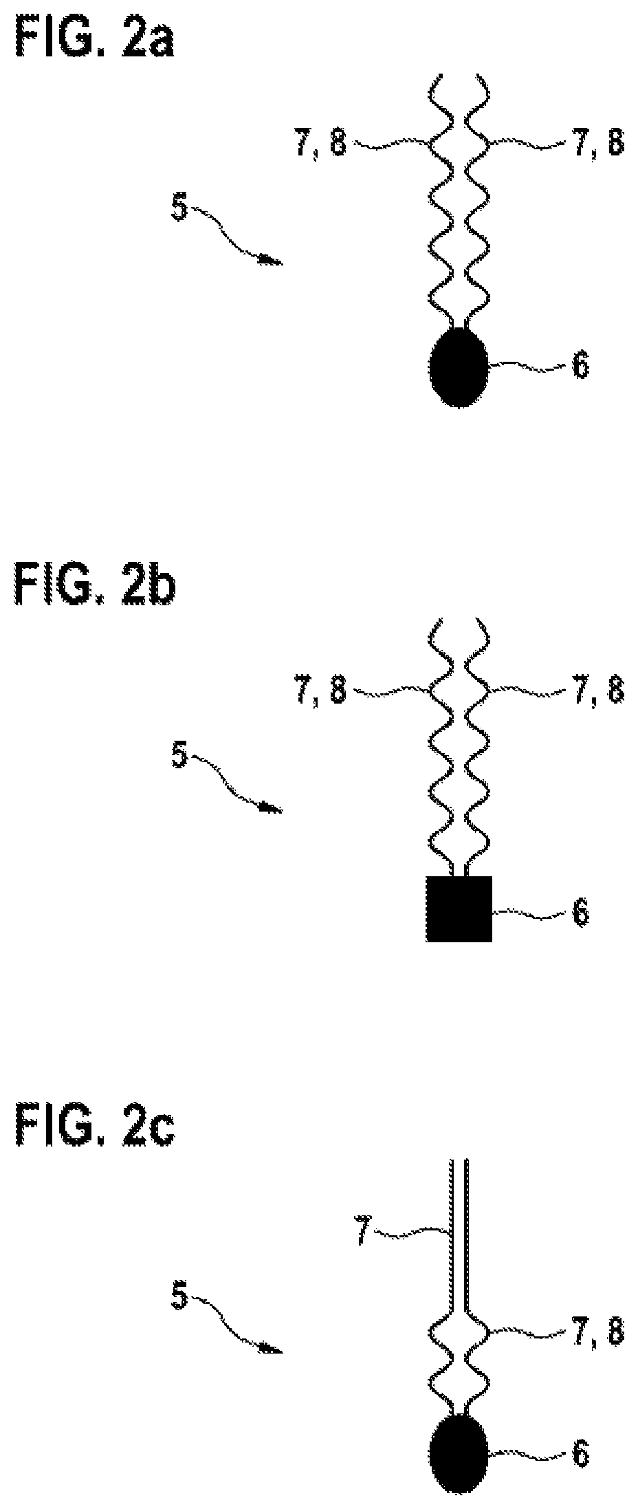
[0040]FIG. 2a illustrates schematically a side view of a temperature sensor 5 in accordance with the invention. The temperature sensor 5 comprises a sensor head 6, which has an oval longitudinal section, and two connections wires 7, which are arranged adjacent to one another and are electrically coupled to the sensor head 6 and are each configured as spring elements 8 that are twisted separately from one another.

second embodiment

[0041]a temperature sensor 5 in accordance with the invention and illustrated schematically in a side view in FIG. 2b comprises a sensor head 6, which has a rectangular or square longitudinal section, and two connection wires 7, which are arranged adjacent to one another and are electrically coupled to the sensor head 6 and are each configured as spring elements 8 that are twisted separately from one another.

third embodiment

[0042]a temperature sensor 5 in accordance with the invention is illustrated schematically in a side view in FIG. 2c. The temperature sensor 5 comprises a sensor head 6, which has an oval longitudinal section, and two connection wires 7, which are arranged adjacent to one another and are electrically coupled to the sensor head 6. The connection wires 7 are each configured in a region that is adjacent to the sensor head 6 as twisted spring elements 8. It is naturally possible in accordance with the invention that a sensor head 6 in this embodiment may also have a rectangular or square longitudinal section.

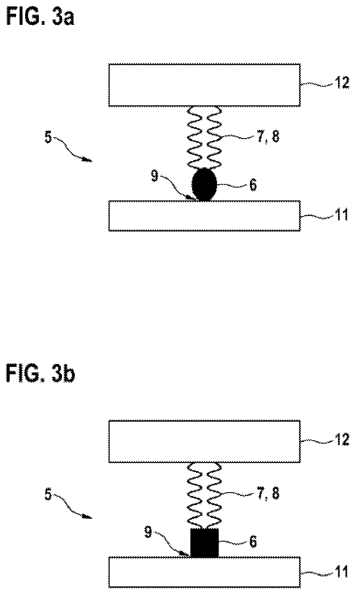
[0043]FIG. 3a illustrates schematically a side view of a sensor arrangement having a temperature sensor 5 in accordance with the first embodiment. Ends that are remote from the sensor head 6, which has an oval longitudinal section, and are part of the connection wires 7, which are twisted separately and arranged adjacent to one another parallel with the spring elements 8, are electr...


PUM

PropertyMeasurementUnit
temperatureaaaaaaaaaa
voltagesaaaaaaaaaa
currentsaaaaaaaaaa

Abstract

The invention relates to a temperature sensor (5) for measuring a temperature of a battery system (1) for storing electrical energy and also for supplying an electric motor of a motor vehicle with electrical energy. The temperature sensor (5) has a sensor head (6) and connection wires (7) electrically coupled to the sensor head. At least one of the connection wires (7) is at least partially formed as a spring element (8) or forms at least part of a spring element (8), wherein the spring element (8) is formed as a helical spring or as twisted. The invention further relates to a battery system (1) with at least one temperature sensor (5) for measuring a temperature of at least one battery cell (3), wherein the temperature sensor (5) has at least one spring element (8), which is mechanically attached to a sensor head (6) of the temperature sensor (5) and is fastened to the battery management system (4) in such a way that the sensor head (6) is pressed by the spring element (8) onto a measuring point (9) on a battery unit (2) of the battery system (1). The invention also relates to a method for fitting such a battery system (1).

Description

BACKGROUND OF THE INVENTION[0001]Battery systems, in particular Li-ion battery systems, are often used as energy storage devices for a drive motor in hybrid or electric vehicles. Known Li-ion battery systems comprise a plurality of Li-ion battery cells that are electrically connected to one another in series and / or in parallel. In order to ensure operational safety, battery systems of this type comprise a battery management system by means of which it is possible to monitor the battery cells or parameters of the battery cells, such as voltages, currents and charges.[0002]In order to ensure an optimum performance and to ensure that the battery cells age as little as possible and to ensure a high degree of operational safety, it has been proven to monitor temperatures of battery systems and thus to be able to control in a closed-loop manner the operation of the battery system within a predetermined temperature range. In so doing, it is important to monitor the temperature of the indiv...

Claims


Application Information

Patent Timeline
Patent Type & Authority Patents(United States)
IPC IPC(8): H01M10/48H01M2/10H01M10/625H05K1/18H01M10/613G01R31/36B60L50/64
CPCH01M10/486H05K1/18H01M10/613G01R31/36H01M2/1077H05K2201/10151H01M2220/20H01M10/625Y02E60/10H01M50/204H01M50/249B60L50/64Y02T10/70
Inventor LORENZ, LISAOTTO, ANDREASJASCH, WALTER
Owner ROBERT BOSCH GMBH
Why Eureka
Try Eureka