

Rubber member for laser bonding and shoe
a technology of rubber members and adhesives, applied in the field of rubber members, can solve the problems of long time, and inability to coat complicated shaped bonding surfaces with solvents, and achieve the effects of excellent mechanical strength, excellent laser light transmittance, and relatively reduced irradiation time required to bond rubber members to adhesives
- Summary
- Abstract
- Description
- Claims
- Application Information
AI Technical Summary
Benefits of technology
Problems solved by technology
Method used
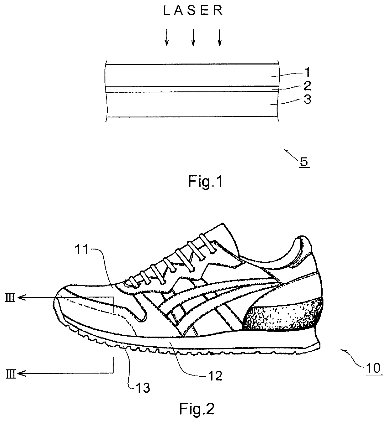
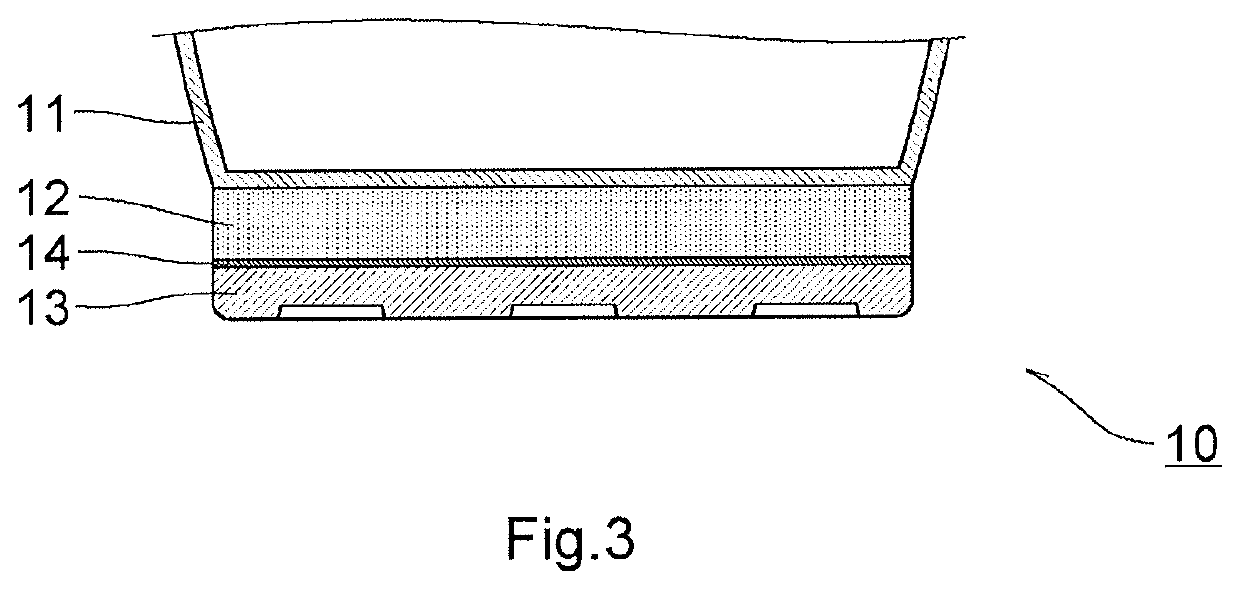
Image

Examples
example 1
[0099]The materials were blended at the ratio shown in the composition in Table 1, and mixed at 80° C. by using a kneader (Model DSS-10 MWB-E) to thereby obtain a mixture.
[0100]Next, the mixture was pressed at 160° C. under a pressure of about 14.7 MPa for about 20 minutes by using a pressing machine to prepare a sheet having a thickness of 2 mm. Further, the sheet was shaped to have a longitudinal length of 50 mm and a lateral length of 20 mm.
[0101]The laser light transmittance of the sheet was measured. The results are shown in Table 1.
[0102]In the composition in Table 1, the unit of the blended amount of each material is part by mass (the same applies to Tables 2 to 4 and 6).
examples 2 to 15
[0103]Sheets having a thickness of 2 mm were prepared in the same manner as in Example 1 except that the materials were blended at the ratio shown in the compositions in Tables 1 to 3. The laser light transmission of each sheet was measured. The results are shown in those Tables.
examples 16 to 20
[0111]Sheets having a thickness of 2 mm were prepared in the same manner as in Example 1 except that the materials were blended at the ratio shown in the compositions in Table 4. The laser light transmission of each sheet was measured. The results are shown in Table 4.
[0112]
TABLE 4ExampleExampleExampleExampleExamplecomposition1617181920Butadiene507030RubberStyrene-100ButadieneRubberIsoprene100503070RubberSilica 13030303030(averageparticle size:12 nm)Crosslinker0.250.50.40.350.45(Dicumyl-Peroxide)Stearic Acid11111Softener66666Laser Light5773777275Transmit-tance (%)
[0113]The results from Examples 16 to 20 show that when the rubber ingredient other than butadiene rubber or two kinds of rubber ingredients is(are) used, a rubber member having a laser light transmittance of 30% or more can be obtained.
[0114]Next, the mechanical strengths of rubber sheets of Examples 2, 5, 8, 15, 16 and 18 were measured. The results are shown in Table 5. All the sheets had a mechanical strength required as...
PUM
| Property | Measurement | Unit |
|---|---|---|
| particle size | aaaaa | aaaaa |
| particle size | aaaaa | aaaaa |
| particle size | aaaaa | aaaaa |
Abstract
Description
Claims
Application Information