Resonance device

a resonance device and resonance technology, applied in the direction of mechanical vibration separation, impedence network, electrical apparatus, etc., can solve the problems of substrate breakage, substrate deformation, and substrate damage, so as to reduce the size of the resonance device and suppress the occurrence of deformation and breakag

Active Publication Date: 2020-06-02
MURATA MFG CO LTD
View PDF22 Cites 2 Cited by
  • Summary
  • Abstract
  • Description
  • Claims
  • Application Information

AI Technical Summary

Benefits of technology

[0007]The present disclosure has been made in light of the above-described situation, and it is an object of the disclosed resonance devices to realize a reduction in the size of a resonance device and to suppress occurrence of deformation and breakage of a resonance device.
[0009]According to the present disclosure, in a resonance device, a reduction in the size of the resonance device is realized, and occurrence of deformation and breakage is suppressed.

Problems solved by technology

As a result, deformation, such as warpage, may occur in the substrates or that the substrates will break due to an impact generated when an electronic device falls on the ground, for example.

Method used


Image

  • Resonance device
  • Resonance device
  • Resonance device

Examples


first embodiment

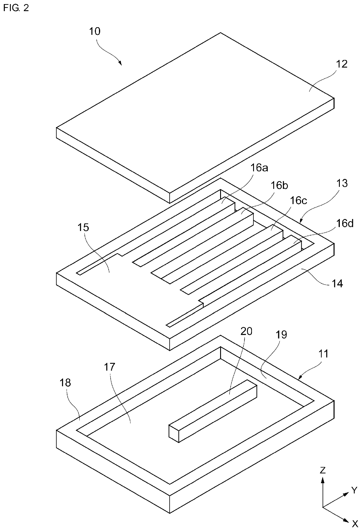
[0023]FIG. 2 is an exploded perspective view schematically illustrating the structure of the resonance device 10 according to the As illustrated in FIG. 2, the resonator 13 includes a support frame 14 extending along an XY plane of the rectangular coordinate system of FIG. 2 so as to have a rectangular frame-like shape, a base portion 15 extending from an end of the support frame 14 along the XY plane so as to have a flat plate-like shape in the support frame 14, and a plurality of vibration arms 16a to 16d extending along the XY plane, each of the plurality of vibration arms 16a to 16d having a fixed end, which is connected to an end of the base portion 15, and a free end. In the present embodiment, four vibration arms 16a to 16d extend parallel to the Y-axis. However, it is noted that the number of the vibration arms is not limited to four and may be set to any number that is, for example, four or larger.

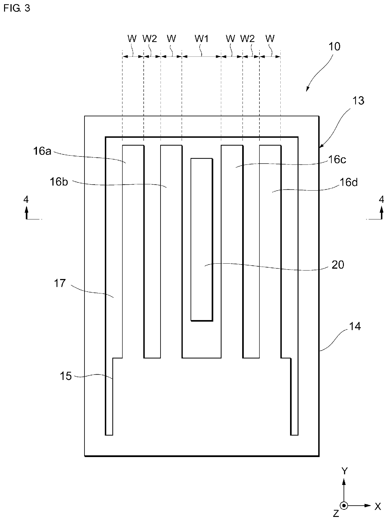
[0024]FIG. 3 is a plan view of the resonance device 10 from which the upper ...

third embodiment

[0043]FIG. 9 is a cross-sectional view schematically illustrating the structure of a resonance device 10 according to a As illustrated in FIG. 9, in addition to the protruding portion 20 of the lower substrate 11, a protruding portion 40 may be formed on the inner surface of the upper substrate 12. Similar to the protruding portion 20, the protruding portion 40 is formed in a rectangular columnar shape extending in the Y-axis direction. In the present embodiment, the protruding portion 40 is formed on the upper substrate 12 so as to be located at a position facing the protruding portion 20, and the protruding portion 40 is connected to the protruding portion 20. Thus, the protruding portion 40 enters the gap between the inner vibration arms 16b and 16c.

second embodiment

[0044]As is clear from FIG. 9, it is desirable that the protruding portion 20 and the protruding portion 40 be joined to each other by the Au joining film 26 and the Sn joining film 27. In the structure a protruding portion is formed on both the lower substrate 11 and the upper substrate 12, and thus, the rigidity of the substrates can be further improved. Note that the protruding portion 20 and the protruding portion 40 do not need to be formed at positions where they exactly face each other in the Z-axis direction and may face each other at positions where they are displaced from each other, and a portion of the protruding portion 20 and a portion of the protruding portion 40 may be joined to each other. In addition, the protruding portion 20 and the protruding portion 40 do not need to be formed at positions where they face each other.

[0045]In the third embodiment illustrated in FIG. 9, the protruding portion 40 of the upper substrate 12 is formed integrally with a Si layer havi...


PUM

PropertyMeasurementUnit
thicknessaaaaaaaaaa
thicknessaaaaaaaaaa
lengthaaaaaaaaaa

Abstract

A resonance device is provided with a reduced size and also suppresses the occurrence of deformation and breakage during operation. The resonance device includes a lower substrate, an upper substrate that defines a vibration space between the lower substrate and the upper substrate, a protruding portion that is formed on an inner surface of the lower or upper substrates. Moreover, a resonator is disposed in the vibration space and includes a base portion and vibration arms that extend in parallel to one another from the base portion along the inner surface of the lower substrate or the inner surface of the upper substrate and that vibrate in a vertical direction toward the inner surface of the lower substrate or the inner surface of the upper substrate.

Description

CROSS REFERENCE TO RELATED APPLICATIONS[0001]The present application is a continuation of PCT / JP2015 / 076690 filed Sep. 18, 2015, which claims priority to Japanese Patent Application No. 2014-199030, filed Sep. 29, 2014, the entire contents of each of which are incorporated herein by reference.TECHNICAL FIELD[0002]The present disclosure relates to a resonance device in which a plurality of vibration arms vibrate in an out-of-plane bending vibration mode.BACKGROUND[0003]Currently, resonance devices manufactured using micro-electromechanical systems (MEMS) technology have been used as, for example, timing devices. Conventional resonance devices are mounted onto printed wiring boards, which are incorporated into electronic devices such as smartphones. Such a resonance device includes a lower substrate, an upper substrate that defines a cavity between the lower substrate and the upper substrate. Moreover, a resonator is disposed in the cavity between the lower substrate and the upper sub...

Claims


Application Information

Patent Timeline
Patent Type & Authority Patents(United States)
IPC IPC(8): H03H9/10H03H3/007B06B1/06H03H9/21H03H9/24H03H9/02
CPCB06B1/0603H03H9/2447H03H3/0072H03H9/1057H03H9/2489H03H2009/02299
Inventor GOTO, YUICHIHIROTA, WAKANA
Owner MURATA MFG CO LTD
Why Eureka
Try Eureka