Dielectric resonator antenna

a resonator antenna and dielectric technology, applied in the direction of antennas, basic electric elements, polarised antenna unit combinations, etc., can solve the problem of bulkyness

Active Publication Date: 2020-06-09
CITY UNIVERSITY OF HONG KONG
View PDF14 Cites 1 Cited by
  • Summary
  • Abstract
  • Description
  • Claims
  • Application Information

AI Technical Summary

Problems solved by technology

Problematically, however, existing structures for unilateral radiation require the use of cavities and relatively large ground planes, and hence are rather bulky.

Method used


Image

  • Dielectric resonator antenna
  • Dielectric resonator antenna
  • Dielectric resonator antenna

Examples


Embodiment Construction

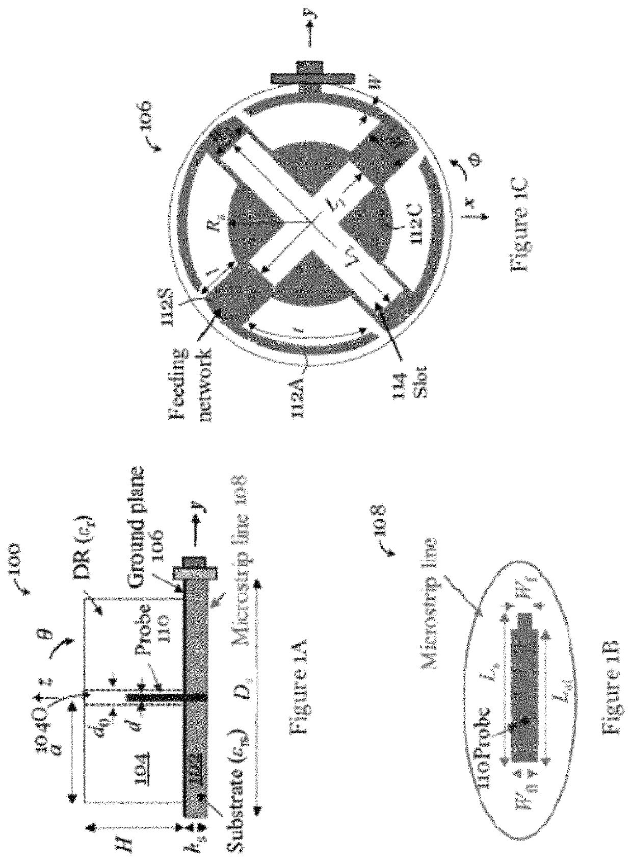
[0058]FIGS. 1A to 1C illustrate a dielectric resonator antenna 100 in one embodiment of the invention. The dielectric resonator antenna 100 is a circularly polarized unilateral dielectric resonator antenna arranged to provide unilateral circularly polarized radiation. The antenna 100 includes a dielectric substrate 102 with a ground plane 106 on one side, and a dielectric resonator element 104 arranged on the ground plane 106. In the present embodiment, the dielectric resonator element 104 includes a cylindrical body with a through-opening 1400 formed in the body. The through-opening 1400 may be generally cylindrical, and has a diameter do. The cylindrical dielectric resonator element 104 has a dielectric constant εr, radius a, and height H. The dielectric substrate 102 with ground plane 106 is also cylindrical, with a generally circular cross section. The substrate 102 has a dielectric constant of εrs, thickness of hs, and diameter of Ds, as illustrated in FIG. 1A. Preferably, a ra...


PUM


Abstract

A dielectric resonator antenna having a dielectric substrate with a ground plane and a dielectric resonator element arranged on the ground plane includes a conductive feeding assembly operable to excite one or more dielectric resonator modes of the dielectric resonator element for generation of a first circularly polarized electromagnetic field, and a radiating arrangement operable to produce a second circularly polarized electromagnetic field complementary to the first circularly polarized electromagnetic field. The first and second circularly polarized electromagnetic fields, when combined, are arranged to provide a unilateral circularly polarized electromagnetic field.

Description

TECHNICAL FIELD[0001]The invention relates to a dielectric resonator antenna and particularly, although not exclusively, to a unilateral circularly polarized dielectric resonator antenna that has a rather compact construction.BACKGROUND[0002]Unidirectional antenna has been widely investigated due to its capability of confining or concentrating radiation in a desired direction. Conventionally, complementary antenna has been used to obtain a unidirectional radiation pattern.[0003]A unidirectional radiation pattern can be broadly classified into two types: broadside radiation and lateral radiation. For broadside radiation, magneto-electric dipoles have been used in various applications including wideband, low-profile, diversity, dual-band, circular-polarization, and reconfiguration applications. On the other hand, for unilateral radiation, structures with cavity-backed slot-monopole configurations have been used.[0004]In some applications, lateral radiation may be more preferred than t...

Claims


Application Information

Patent Timeline
Patent Type & Authority Patents(United States)
IPC IPC(8): H01Q9/04
CPCH01Q9/045H01Q9/0492H01Q1/36H01Q1/38H01Q1/50H01Q21/24
Inventor LEUNG, KWOK WAGUO, LEI
Owner CITY UNIVERSITY OF HONG KONG
Why Eureka
Try Eureka