Modulation apparatus

a technology which is applied in the field of modulation apparatus and modulation method, can solve problems such as difficulties in realization, and achieve the effects of low cost, wide resulting bandwidth, and high range resolution

Active Publication Date: 2020-06-09
SONY CORP
View PDF36 Cites 2 Cited by
  • Summary
  • Abstract
  • Description
  • Claims
  • Application Information

AI Technical Summary

Benefits of technology

[0028]The present disclosure provides a low cost, narrow-band modulation capability for a transmitter operating at mm-wave frequency. The modulation apparatus of the present disclosure can be applied in both continuous wave and frequency-modulated transmitters. If an apparatus according to the present disclosure is included in a frequency-modulated transmitter, it becomes possible to obtain a wide resulting bandwidth. This is advantageous for a high range resolution in radar applications.
[0029]In comparison to prior art techniques which offer modulation capability either at high costs by using a wide-band analogue modulator or which use delta-sigma modulation with the drawback of always generating a double side band signal the present disclosure allows reducing manufacturing costs and increasing spectrum use efficiency. In particular, the use of a switch instead of an analogue multiplier for the multiplicative combiner may allow reducing manufacturing costs and power consumption. If a complex, i.e. a single side band, modulation instead of double side band modulation is used it becomes possible to double the spectral efficiency.

Problems solved by technology

Additional modulation could be done with a linear modulator, but is difficult to realize.

Method used


Image

  • Modulation apparatus
  • Modulation apparatus
  • Modulation apparatus

Examples


embodiment 1

2. Modulation apparatus as defined in embodiment 1, wherein the delay component includes at least one of a delay line and / or an analogue filter.

[0095]3. Modulation apparatus as defined in any of the preceding embodiments, further comprising an oscillator for providing the carrier signal, in particular a voltage controlled oscillator for providing an adjustable carrier signal or a local oscillator for providing a constant frequency carrier signal.

4. Modulation apparatus as defined in any of the preceding embodiments, wherein the delay component is located in a signal path from the second multiplicative combiner to the output combiner and / or in a signal path from the oscillator to the second multiplicative combiner.

5. Modulation apparatus as defined in any of the preceding embodiments, wherein

[0096]the first multiplicative combiner includes a Gilbert cell for inverting the carrier signal depending on the digital in-phase signal; and

[0097]the second multiplicative combiner includes a G...

embodiment 9

10. Radar system as defined in embodiment 9, wherein

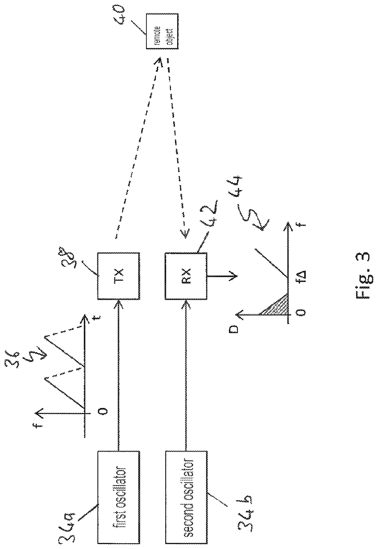
[0105]the baseband signal has a periodically changing frequency or a temporarily constant frequency; and

[0106]the processor is configured to determine a distance of the remote object with respect to the radar system in addition to the relative velocity.

11. Radar system as defined in embodiments 9-10, comprising:

[0107]at least one further modulation apparatus as defined in any of the embodiments 1-8, wherein the first modulation apparatus and the at least one further modulation apparatus make use of the same carrier signal; and

[0108]at least one further transmit antenna for transmitting the at least one further transmit signal of the at least one further modulation apparatus; wherein

[0109]the processor is configured to determine a relative velocity and / or distance of the remote object with respect to the radar system based on the reflected signals.

12. Communication apparatus, comprising:

[0110]a modulation apparatus as defined in any...

embodiment 12

13. Communication apparatus as defined in embodiment 12, further comprising a band-pass filter for filtering the transmit signal.

14. Modulation method, comprising the steps of

[0112]providing a digital in-phase signal based on a modulation of an in-phase component of a baseband signal;

[0113]providing a digital quadrature signal based on a modulation of a quadrature component of the baseband signal;

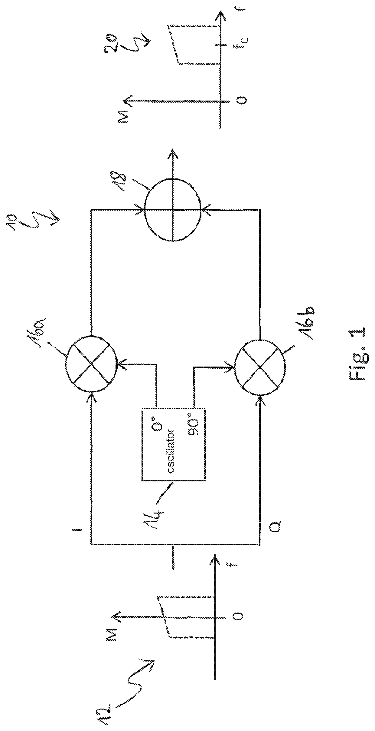
[0114]combining a carrier signal with the digital in-phase signal and providing an in-phase output signal;

[0115]combining the carrier signal with the digital quadrature signal and providing a quadrature output signal;

[0116]generating a 90° phase shift between the in-phase output signal and the quadrature output signal; and

[0117]combining the in-phase output signal and the quadrature output signal and generating a transmit signal.


PUM


Abstract

Modulation apparatus, comprising: a first delta-sigma modulator for providing a digital in-phase signal based on a modulation of an in-phase component of a baseband signal; a second delta-sigma modulator for providing a digital quadrature signal based on a modulation of a quadrature component of the baseband signal; a first multiplicative combiner for combining a carrier signal with the digital in-phase signal and for providing an in-phase output signal; a second multiplicative combiner for combining the carrier signal with the digital quadrature signal and for providing a quadrature output signal; a delay component for generating a 90° phase shift between the in-phase output signal and the quadrature output signal; and an additive output combiner for combining the in-phase output signal and the quadrature output signal and generating a transmit signal.

Description

BACKGROUND[0001]Field of the Disclosure[0002]The present disclosure relates to a modulation apparatus and modulation method. The present disclosure further relates to a radar system as well as to a communication system including said modulation apparatus.[0003]Description of Related Art[0004]Wireless signal transmission forms the basis for a range of applications in the fields of radar and communications. Due to the increasing number of applications making use of wireless signal transmission, techniques for using the spectrum efficiently and for reducing manufacturing costs have become more and more important.[0005]There is, however, a need for further improvements in this field in particular with respect to manufacturing costs and efficient spectrum use.[0006]The “background” description provided herein is for the purpose of generally presenting the context of the disclosure. Work of the presently named inventor(s), to the extent it is described in this background section, as well ...

Claims


Application Information

Patent Timeline
Patent Type & Authority Patents(United States)
IPC IPC(8): H04L27/20G01S7/35G01S13/02G01S13/58
CPCG01S7/35H04L27/205G01S13/0209G01S13/583
Inventor SPALINK, GERD
Owner SONY CORP
Why Eureka
Try Eureka