
Base station device, terminal device and transmission control method

a technology of transmission control and base station, which is applied in the direction of spatial transmit diversity, connection management, diversity/multi-antenna systems, etc., can solve the problems of reducing throughput, wasting time, and wasting resources, so as to shorten the waiting time

Active Publication Date: 2020-06-16
PANASONIC CORP
View PDF15 Cites 0 Cited by
  • Summary
  • Abstract
  • Description
  • Claims
  • Application Information

AI Technical Summary

Benefits of technology

The invention aims to reduce unnecessary transmission of signals to areas where there are no terminal apparatuses. This saves time for the terminal apparatuses to receive the signals. It does not rely on historical information, but uses it to determine which signals should be eliminated from transmission. This ensures that signals are only transmitted in directions where terminal apparatuses are present.

Problems solved by technology

However, when time-divisionally transmitting a control signal for synchronization by forming transmission beams so as to make a rotation of a beam direction as taught in the above-described prior art document, it takes a longer time to complete each scan by transmitting the control signal for synchronization over an entirety of a cell, resulting in a longer waiting time until each user terminal receives the control signal for synchronization, which means it takes a longer time to attain synchronization, causing a problem that time for user data transmission is made shorter to thereby lower throughput.
However, this method inconveniently requires more resources to be used as control channels, leading to lower throughput.
Moreover, the above-described prior art, in which a beam width is adjusted in a stepwise manner when performing a scan, involves a problem that a transmission beam direction cannot always be controlled to be a proper direction towards where one or more user terminals are present because reachable distance of the transmission beams varies depending on the beam width and each user terminal can move.

Method used


Image

  • Base station device, terminal device and transmission control method
  • Base station device, terminal device and transmission control method
  • Base station device, terminal device and transmission control method

Examples


first embodiment

Modification of First Embodiment

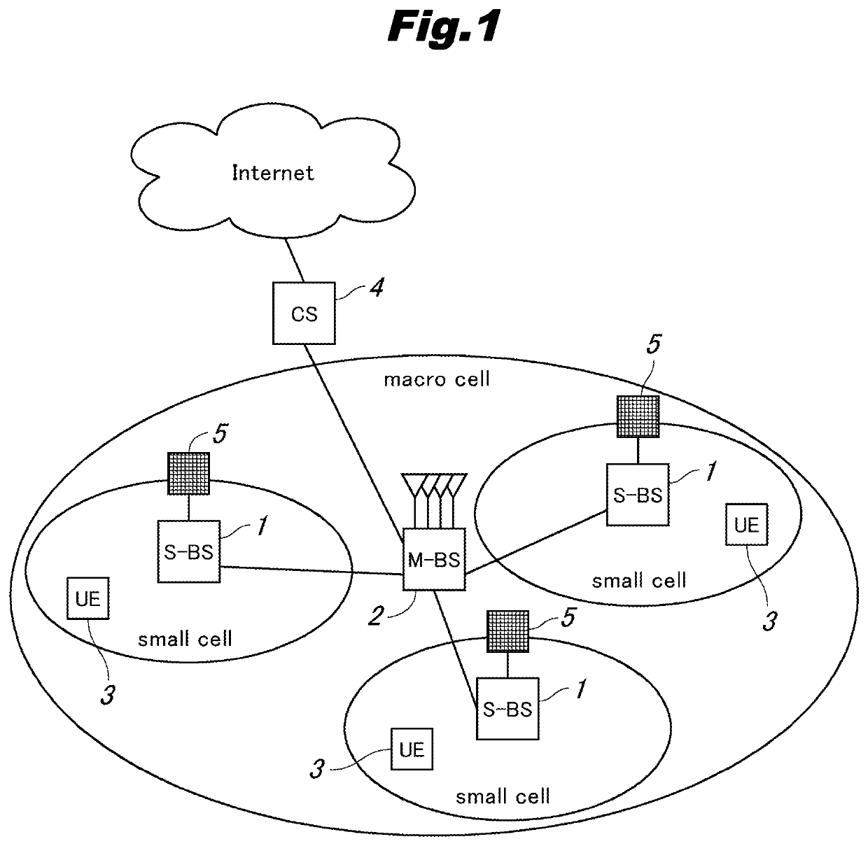
[0156]Next, a modification of the first embodiment of the present invention will be described. FIG. 12 is an explanatory view showing an example of historical information according to a modification of the first embodiment of the present invention. Except for what will be discussed here, the configuration of the present embodiment is the same as that of the first embodiment.

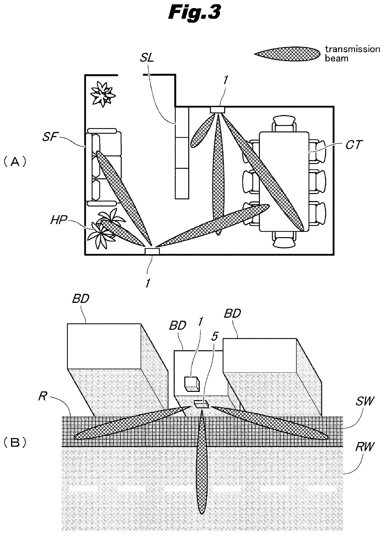
[0157]In cases where a moving obstacle exists, when the obstacle moves into a radio wave propagation path between a small cell base station 1 and a user terminal 3, communication is disconnected between the user terminal and the small cell station, and when the obstacle moves past the radio wave propagation path, the communication can be restored. When a person carrying a user terminal 3 moves so that the user terminal 3 moves into an area where radio wave paths are blocked by an obstacle, communication is disconnected between the user terminal and the small cell base station 1, an...

second embodiment

[0163]Next, a second embodiment of the present invention will be described. FIG. 13 is a diagram showing a general configuration of a communication system according to a second embodiment of the present invention. Except for what will be discussed here, the configuration of the present embodiment is the same as that of the first embodiment.

[0164]In the first embodiment of the present invention, beam control for controlling transmission beams formation based on transmission schedule information is applied to transmission in a cellular mobile communication system, in particular, applied to transmission of down control signals from a small cell base station 1 using wireless communication technology for 5G systems (fifth generation mobile communication systems), whereas, in the present embodiment, beam control for controlling transmission beams formation based on transmission schedule information is applied to transmission of down control signals from an access point 101 (base station a...

third embodiment

[0189]Next, a third embodiment of the present invention will be described. FIG. 15 is a diagram showing a general configuration of a communication system according to the third embodiment of the present invention. FIG. 16 is an explanatory view showing an example of installation of the first base stations 201 and the second base station 202. Except for what will be discussed here, the configuration of the present embodiment is the same as that of the first embodiment.

[0190]In the first embodiment, transmission schedule control is applied to transmission of control signals in access networks connecting the small cell base station 1 with the user terminals 3, whereas, in the present embodiment, transmission schedule control is applied to transmission of control signals in backhaul networks connecting the access networks with backbone networks.

[0191]As shown in FIG. 15, a communication system according to the present embodiment includes a first base station 201 (subordinate base statio...


PUM


Abstract

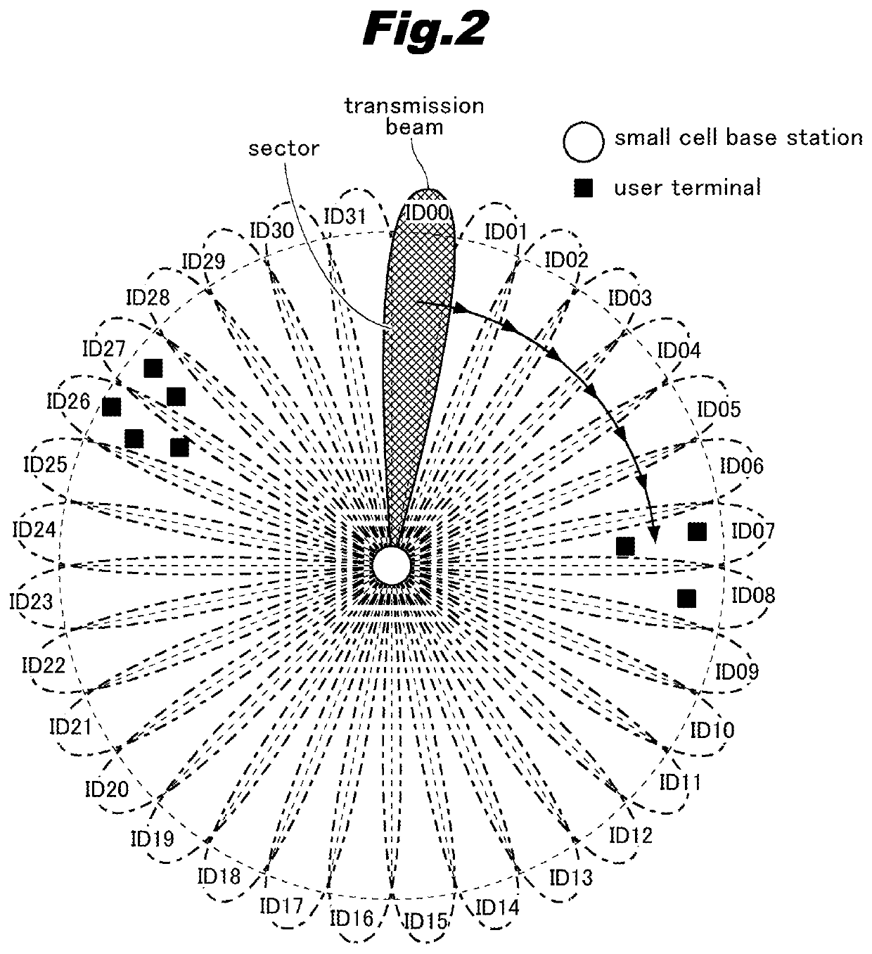
In order to shorten a waiting time until a user terminal receives a down signal transmitted from a base station apparatus and ensure that a transmission beam is transmitted to a direction towards where one or more user terminals are present, a base station for time-divisionally transmitting a down signal to multiple user terminals present in a cell concurrently with changing a transmission beam direction where the down signal is common to the multiple user terminals is provided and includes a wireless communicator configured to time-divisionally transmit the down signal concurrently with changing the transmission beam direction, an information storage configured to store transmission schedule information which specifies transmission timing of the transmission beam, and a controller configured to control, based on the transmission schedule information, the transmission beams when the base station transmits the down signal.

Description

TECHNICAL FIELD[0001]The present invention relates to a base station apparatus for time-divisionally transmitting a down signal to terminal apparatuses and / or subordinate base station apparatus present in a cell concurrently with changing a transmission beam direction wherein the down signal is common to the multiple terminal apparatuses and the multiple subordinate base station apparatuses; a terminal apparatus for transmitting an up signal to and receiving a down signal from a base station apparatus; and a transmission control method used in a base station apparatus for time-divisionally transmitting a down signal to multiple terminal apparatuses present in a cell concurrently with changing a transmission beam direction wherein the down signal is common to the multiple terminal apparatuses.BACKGROUND ART[0002]Recently, adopting Massive-MIMO (Multiple Input Multiple Output) utilizing multi-element antennas in 5G systems (fifth generation mobile communication systems) is under consi...

Claims


Application Information

Patent Timeline
Patent Type & Authority Patents(United States)
IPC IPC(8): H04W16/28H04W72/04H04W72/12H04W64/00H04B7/06
CPCH04W72/0446H04W64/006H04W72/121H04W16/28H04B7/0695H04W72/048H04W76/19H04W48/12H04W72/51
Inventor SHIMIZU, NORIYUKIKATOU, OSAMU
Owner PANASONIC CORP
Learn More