Simplified packer penetrator and method of installation

a packer and penetrator technology, applied in the direction of sealing/packing, coupling device connection, borehole/well accessories, etc., can solve the problems of time-consuming and difficult, and achieve the effect of preventing grit or fluid from damaging the connection and improving the conductivity of the spli

Active Publication Date: 2020-06-23
QUICK CONNECTORS
View PDF9 Cites 2 Cited by
  • Summary
  • Abstract
  • Description
  • Claims
  • Application Information

AI Technical Summary

Benefits of technology

[0011]The present invention is a packer penetrator consisting of three metallic mandrels. The distal mandrel consists of a metallic threaded mandrel through which a stripped armored cable is fed through and seated into that distal mandrel using O-rings, a metallic sleeve and an elastomeric seal. The distal mandrel is filled with epoxy to further seal the mandrel. The cable to be spliced is pulled through the packer and fed through the proximal mandrel. The proximal mandrel either threaded directly into the packer if the diameter of the hole in the packer will allow it or more commonly by using a male to female threaded adapter. The cable is then spliced to the cable from the distal mandrel and inserted into the intermediate mandrel which is either directly threaded onto the proximal mandrel or the male to female crossover, and occasionally instead of a direct thread, a locking nut is used to connect the intermediate mandrel to the proximal mandrel. Before the intermediate mandrel is connected to the proximal mandrel, it is filled with dielectric grease to improve the conductivity of the splice and prevent grit or fluids from damaging the connection.

Problems solved by technology

Previously, connecting an Electrical Submersible Pump cable to a well bore packer was a time consuming and difficult task with the possibility that, once finished, the packer penetrator and splice of the cable would still allow leaks, grime and pressure to travel up the power cable and short or interfere with the operation of the ESP.

Method used


Image

  • Simplified packer penetrator and method of installation
  • Simplified packer penetrator and method of installation
  • Simplified packer penetrator and method of installation

Examples


Embodiment Construction

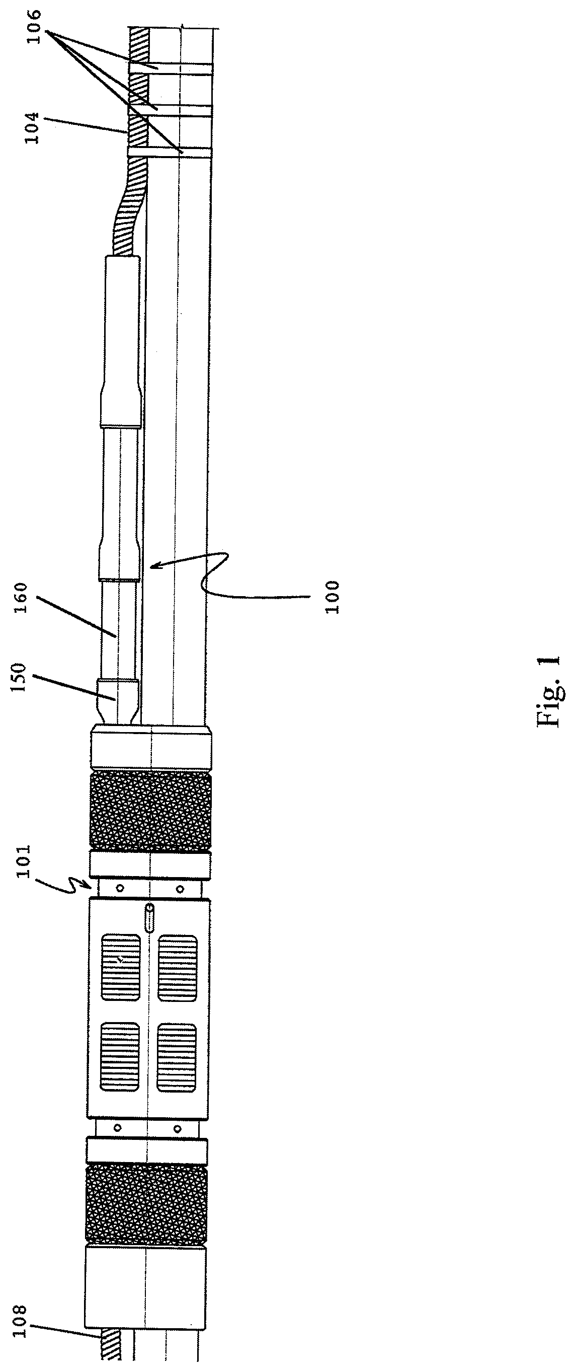
[0014]FIG. 1 shows the packer penetrator 100 of the present invention with the male to female cross-over 150 emerging from the packer 101 and threaded to the proximal mandrel 160. Power cable 104 is banded to the production tubing by bands 106 in a well known manner and connected inside the packer penetrator 100 to the up-hole power cable 108.

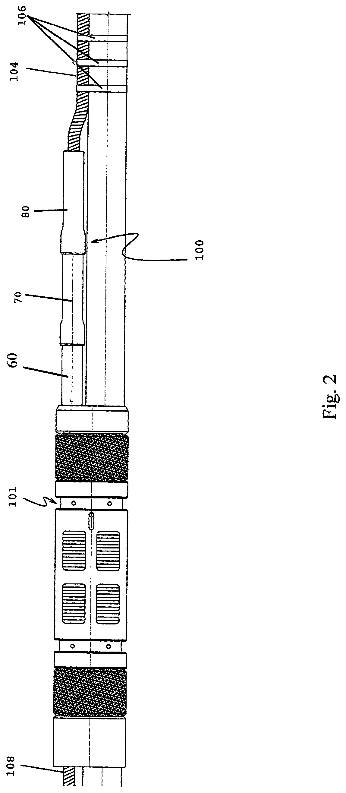
[0015]FIG. 2 shows the packer penetrator 100 of the present invention threaded into an inflatable packer 101 with power cable 108 running into the packer penetrator from topside. Power cable 104 is banded 106 to the production tubing in a manner well known in this art. A proximal mandrel 60 is threaded directly into the packer penetrator 100 and connected to the intermediate mandrel 70 which is connected to the distal mandrel 80.

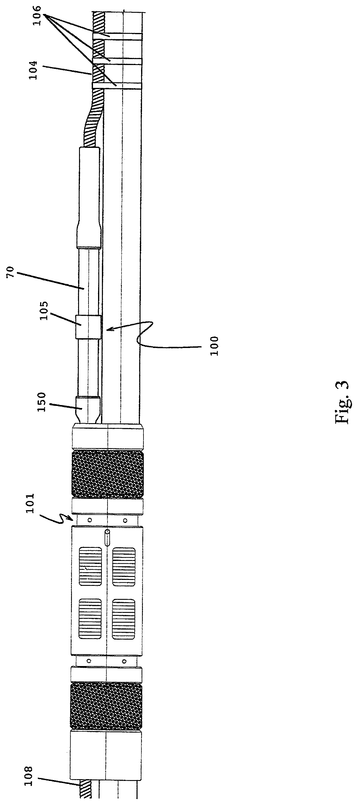
[0016]FIG. 3 shows the packer penetrator 100 of the present invention with the male to female cross-over 150 emerging from the packer 101. Power cable 104 is banded 106 to the production tubing in a well known manner an...


PUM


Abstract

A packer penetrator assembly comprised of a proximal mandrel, an intermediate mandrel and a distal mandrel that can be quickly and efficiently assembled while preventing the migration of gases or fluids up the ESP cable through a well bore packer. These ESP cables can be spliced to power cables passing through a wellbore packer, a sealed electrical connection at a packer assembly. The packer penetrator also offers an adaptive or male to female crossover assembly that allows use of power cables of differing diameters and styles to be joined.

Description

FIELD OF INVENTION[0001]The present invention relates to a new form of electrical connector arrangement; more specifically, to a new packer penetrator permitting electrical conductors to be installed passing through a packer system within a well bore.BACKGROUND OF THE INVENTION[0002]Previously, connecting an Electrical Submersible Pump cable to a well bore packer was a time consuming and difficult task with the possibility that, once finished, the packer penetrator and splice of the cable would still allow leaks, grime and pressure to travel up the power cable and short or interfere with the operation of the ESP. With the present invention, many of these issues are solved; allowing a quicker, cleaner installation of a packer penetrator with the electrical power supply cables that will effectively seal against water, gases and grit found inside the wellbore.BRIEF DESCRIPTION OF THE DRAWINGS[0003]FIG. 1 is a schematic drawing of the reusable packer penetrator of the present invention ...

Claims


Application Information

Patent Timeline
Patent Type & Authority Patents(United States)
IPC IPC(8): E21B17/02H01R13/533E21B33/02H01R13/52
CPCE21B33/02H01R13/5205E21B17/023H01R13/533E21B17/02
Inventor EMERSON, TOD DWILLIAMS, JIMMCCLAIN, ELIZABETH
Owner QUICK CONNECTORS
Why Eureka
Try Eureka