Hydraulic driving apparatus of work machine

a technology of hydraulic driving apparatus and work machine, which is applied in the direction of servomotors, hoisting equipment, transportation and packaging, etc., can solve the problems of inability to avoid excessive cost increases and insufficient installation space, and achieve simple and low-cost configuration and regenerating energy.

Active Publication Date: 2020-07-07
KOBE STEEL LTD
View PDF4 Cites 7 Cited by
  • Summary
  • Abstract
  • Description
  • Claims
  • Application Information

AI Technical Summary

Benefits of technology

[0008]It is therefore an object of the present invention to provide a hydraulic driving apparatus capable of driving multiple driving subjects in a work machine, and regenerating energy thereof by a simple and low-cost configuration.

Problems solved by technology

However, the pump motor constructing the reversible adjustment unit simultaneously has the function as the hydraulic pump and the function as the hydraulic motor, and is thus expensive compared with general hydraulic pump and hydraulic motor.
In the apparatus described in Patent Document 1, each of the rotation driving circuit and the boom driving circuit needs to include the multiple pump motors, the required number of the pump motors is thus large, and consequent excessive increases in cost and installation space cannot be avoided.

Method used


Image

  • Hydraulic driving apparatus of work machine
  • Hydraulic driving apparatus of work machine
  • Hydraulic driving apparatus of work machine

Examples


first embodiment

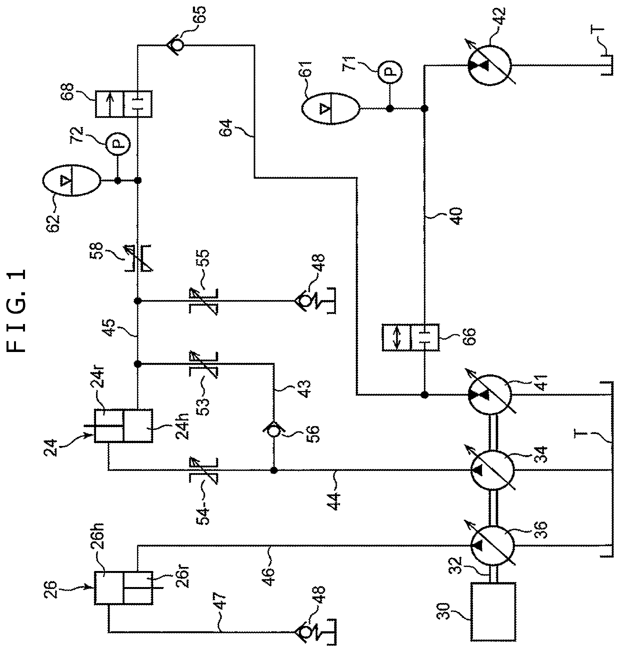
[0023]FIG. 1 shows the hydraulic driving apparatus according to the present invention mounted on the hydraulic shovel. This hydraulic driving apparatus includes multiple hydraulic actuators including the respective cylinders 24, 26, and 28, multiple hydraulic pumps that suck the hydraulic oil from a tank, and discharge the hydraulic oil to the hydraulic actuators for respectively driving the multiple actuators, and a prime mover 30 that is connected to the multiple hydraulic pumps, and drives the hydraulic pumps. Any one of the multiple hydraulic pumps is of a variable displacement type, and the multiple hydraulic pumps include a boom pump 34 that discharges the hydraulic oil for driving the boom cylinder 24, an arm pump 36 that discharges the hydraulic oil for driving the arm cylinder 26, a bucket pump 38 (this bucket pump 38 is not shown in FIG. 1, but is shown in FIG. 2 described later) that drives the bucket cylinder 28, and a first pump motor 41 that discharges the hydraulic oi...

second embodiment

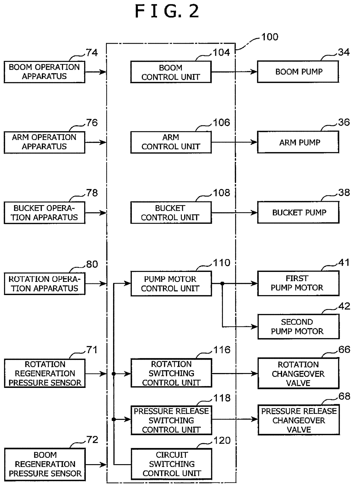
[0068]FIG. 5 shows the controller 100 provided for the apparatus according to the The controller 100 includes an accumulator opening / closing control unit 117 that switches the position of the accumulator opening / closing changeover valve 67 in place of the rotation switching control unit 116. The accumulator opening / closing control unit 117 can switch the rotation regeneration accumulator opening / closing changeover valve 67 to the open position, thereby enabling introduction of the hydraulic oil discharged by the second pump motor 42 in the second pump operation state into the rotation regeneration accumulator 61, and can switch the accumulator opening / closing changeover valve 67 to the closed position, thereby holding the pressure in the rotation regeneration accumulator 61, and surely blocking the inflow of the hydraulic oil, which is supplied from the boom regeneration accumulator 62 to the first pump motor 41, to the rotation regeneration accumulator side.

[0069]The controller 10...

third embodiment

[0073]Though either one of the rotation changeover valve 66 and the accumulator opening / closing changeover valve 67 has the closed position of completely blocking the first pump motor 41 and the rotation regeneration accumulator 61 from each other, an operation pressure of the rotation regeneration accumulator 61 is generally sufficiently higher than an operation pressure of the boom regeneration accumulator 62, and even if the pressure holding valve does not have the closed position, the hydraulic oil can be blocked from flowing from the boom regeneration accumulator 62 into the rotation regeneration accumulator 61. The pressure holding valve may be, for example, a check valve 82 as shown in FIG. 7 as a This check valve 82 is provided between the rotation regeneration accumulator 61 and the first pump motor 41 in the first pump motor line 40, and has a function of permitting the flow of the hydraulic oil from the first pump motor 41 toward the second pump motor 42, and blocking th...


PUM


Abstract

A hydraulic driving apparatus that drives a plurality of driving subjects and regenerates energy thereof. This hydraulic driving apparatus includes: a first pump motor; a second pump motor that is switchable between a state of moving a first driving subject by hydraulic oil discharged from the first pump motor and a state of being operated as a pump by means of energy of the first driving subject; a first pump motor line that couples the first and second pump motors with each other; a first accumulator connected to the first pump motor line; a regeneration subject hydraulic actuator that moves a second driving subject; a second accumulator that receives hydraulic oil from the regeneration subject hydraulic actuator; a second pump motor line that couples the second accumulator with the first pump motor; and a pressure release changeover valve that opens / closes the second pump motor line.

Description

TECHNICAL FIELD[0001]The present invention relates to a hydraulic driving apparatus installed on a work machine such as a hydraulic shovel.BACKGROUND ART[0002]The hydraulic driving apparatus installed on the work machine generally includes a hydraulic pump that discharges hydraulic oil, and a hydraulic actuator that receives the hydraulic oil discharged by the hydraulic pump, and operates so as to move a driving subject, and there has been known a technology of using a so-called pump motor where the hydraulic actuator simultaneously has a pump function and a motor function in order to conversely regenerate an energy by means an external force given by the driving subject in recent years.[0003]For example, Patent Document 1 discloses an apparatus including multiple reversible adjustment units, each of which is a so-called pump motor. This apparatus includes a first reversible adjustment unit E1 and a second reversible adjustment unit E2 provided in a rotation driving circuit that rot...

Claims


Application Information

Patent Timeline
Patent Type & Authority Patents(United States)
IPC IPC(8): E02F9/22E02F9/20F15B1/02B66C13/20B66D1/44F15B21/14F15B11/17
CPCE02F9/2292F15B11/17E02F9/2296F15B21/14E02F9/2217B66D1/44E02F9/2246E02F9/2016F15B1/024B66C13/20E02F9/2239F15B2211/20576F15B2211/611F15B2211/7053F15B2211/212F15B2211/30505F15B2201/51F15B2211/31588F15B2211/761F15B2211/625F15B2211/20546F15B2211/3057F15B2211/20569F15B2211/7135F15B2211/6306F15B2211/30565F15B2211/763F15B2211/3058F15B2211/853F15B2211/7058
Inventor UEMURA, SHOHEISUGANO, NAOKIHORI, NAOTOMAEKAWA, SATOSHI
Owner KOBE STEEL LTD
Why Eureka
Try Eureka