Temperature control of exhaust gas of a transportation refrigeration unit

a refrigeration unit and temperature control technology, applied in the field of refrigeration systems, can solve problems such as fire or damage, and achieve the effect of reducing the temperature of the exhaust gas flow

Active Publication Date: 2020-07-07
CARRIER CORP
View PDF58 Cites 0 Cited by
  • Summary
  • Abstract
  • Description
  • Claims
  • Application Information

AI Technical Summary

Benefits of technology

[0008]Additionally or alternatively, in this or other embodiments a mixing area is located in the nozzle downstream of the exhaust pathway exit, and is configured to allow for mixing of the exhaust gas flow with the cooling airflow to further reduce the temperature of the exhaust gas flow.
[0012]In another embodiment, a method of operating a transportation refrigeration unit includes operating a compressor to compress a flow of refrigerant in the transportation refrigeration unit and operating an engine operably connected to the compressor to drive the compressor. A flow of exhaust gas is directed away from the engine via an exhaust pathway, and a cooling airflow is flowed through a nozzle flowpath defined between the exhaust pathway and a nozzle disposed circumferentially around the exhaust pathway, thereby reducing a temperature of the flow of exhaust gas exiting the exhaust pathway.
[0015]Additionally or alternatively, in this or other embodiments the cooling airflow is mixed with the flow of exhaust gas flow in a mixing area in the nozzle downstream of the exhaust pathway exit to further reduce the temperature of the flow of exhaust gas.

Problems solved by technology

This is problematic when the exhaust is directed toward, for example, foliage or sidewalks, nearby vehicles or the like and may result in fire or damage.

Method used


Image

  • Temperature control of exhaust gas of a transportation refrigeration unit
  • Temperature control of exhaust gas of a transportation refrigeration unit
  • Temperature control of exhaust gas of a transportation refrigeration unit

Examples


Embodiment Construction

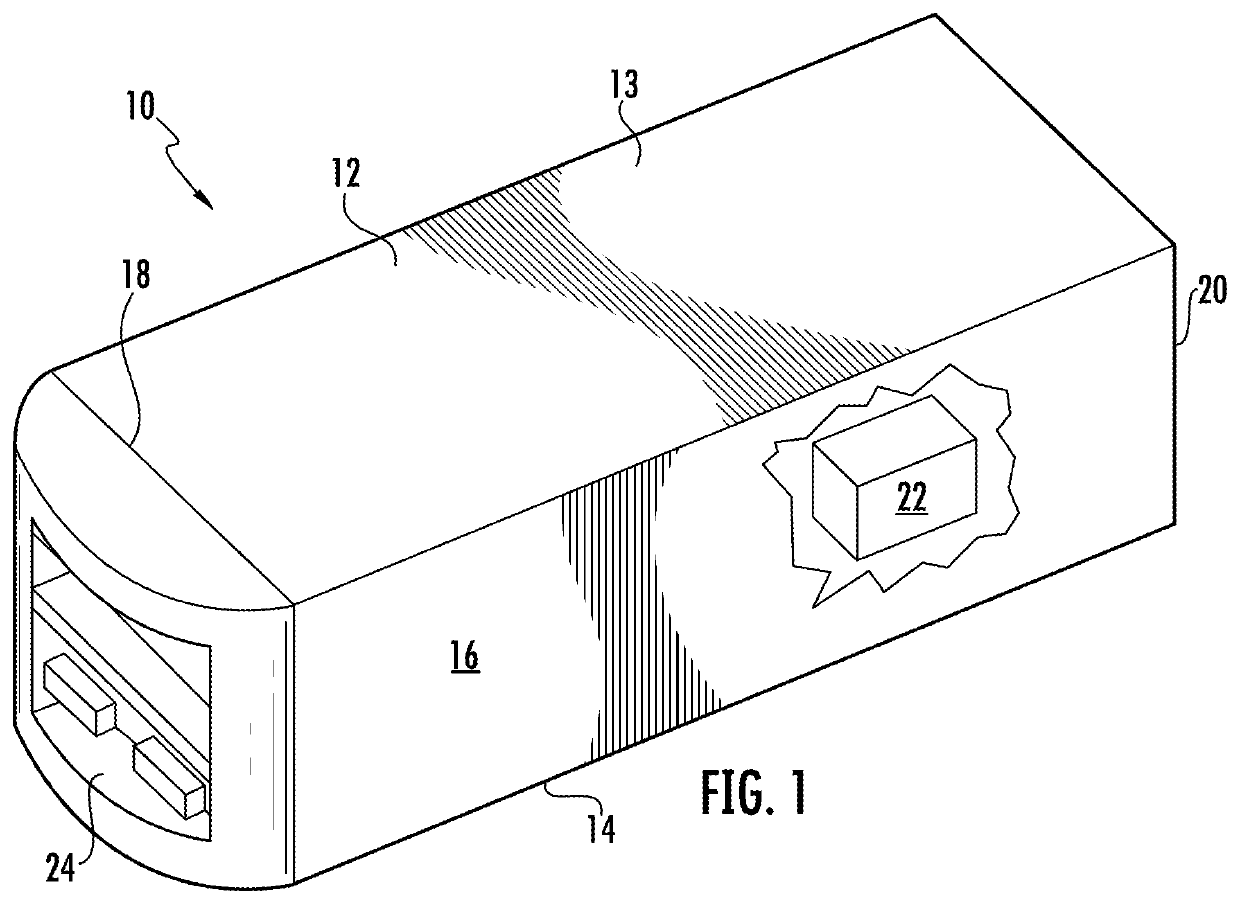
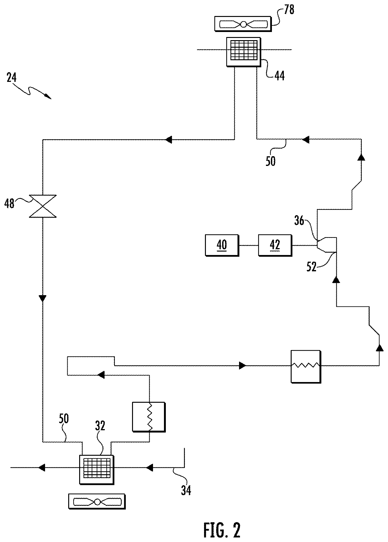
[0028]Shown in FIG. 1 is an embodiment of a refrigerated cargo compartment 10, for example, a refrigerated truck or trailer. The refrigerated cargo compartment 10 is formed into a generally rectangular construction, with a top wall 12, a directly opposed bottom wall 14, opposed side walls 16 and a front wall 18. The cargo compartment 10 further includes a door or doors (not shown) at a rear wall 20, opposite the front wall 18. The cargo compartment 10 is configured to maintain a cargo 22 located inside the cargo compartment 10 at a selected temperature through the use of a refrigeration unit 24 located at the cargo compartment 10. The cargo compartment 10 is utilized to transport the cargo 22. The refrigeration unit 24 is located at the front wall 18, and includes an evaporator 32 that receives an airflow 34 (shown in FIG. 2) from inside the cargo compartment 10 and cools it via thermal energy exchange between the airflow 34 and refrigerant flowing through the evaporator 32. The coo...


PUM


Abstract

A transportation refrigeration unit includes an evaporator circulating a flow of refrigerant therethrough to cool a flow of supply air flowing over the evaporator, a compressor in fluid communication with the evaporator to compress the flow of refrigerant, and an engine operably connected to the compressor to drive operation of the compressor. The engine includes an exhaust pathway to direct an exhaust gas flow from the transportation refrigeration unit, and a nozzle extending circumferentially around the exhaust pathway defining a nozzle flowpath between the exhaust pathway and the nozzle, the nozzle configured to flow a cooling airflow along the nozzle flowpath to reduce a temperature of the exhaust gas flow.

Description

CROSS REFERENCE TO RELATED APPLICATIONS[0001]This application is a National Stage application of PCT / US2016 / 059658, filed Oct. 31, 2016, which claims the benefit of U.S. Provisional Application No. 62 / 256,493, filed Nov. 17, 2015, both of which are incorporated by reference in their entirety herein.BACKGROUND[0002]The subject matter disclosed herein relates to refrigeration systems. More specifically, the subject matter disclosed herein relates to refrigeration of cargo compartments of trucks or trailers.[0003]A typical refrigerated truck or truck trailer, such as those utilized to transport a cargo, includes a refrigeration unit located at one end of the cargo compartment. The refrigeration unit includes a compressor, condenser, expansion valve and evaporator serially connected by refrigerant lines in a closed refrigerant circuit in accord with known refrigerant vapor compression cycles. The evaporator is located in a compartment that requires cooling, such as a cargo compartment o...

Claims


Application Information

Patent Timeline
Patent Type & Authority Patents(United States)
IPC IPC(8): F01N3/05F01N13/08F25D11/00
CPCF25D11/003F01N13/082F01N3/05Y02T10/20F01N2270/02F01N2590/08F01N2240/20Y02T10/12
Inventor SWAB, MICHAEL
Owner CARRIER CORP
Why Eureka
Try Eureka