X-ray device, X-ray irradiation method, and manufacturing method for structure
- Summary
- Abstract
- Description
- Claims
- Application Information
AI Technical Summary
Benefits of technology
Problems solved by technology
Method used
Image

Examples
first embodiment
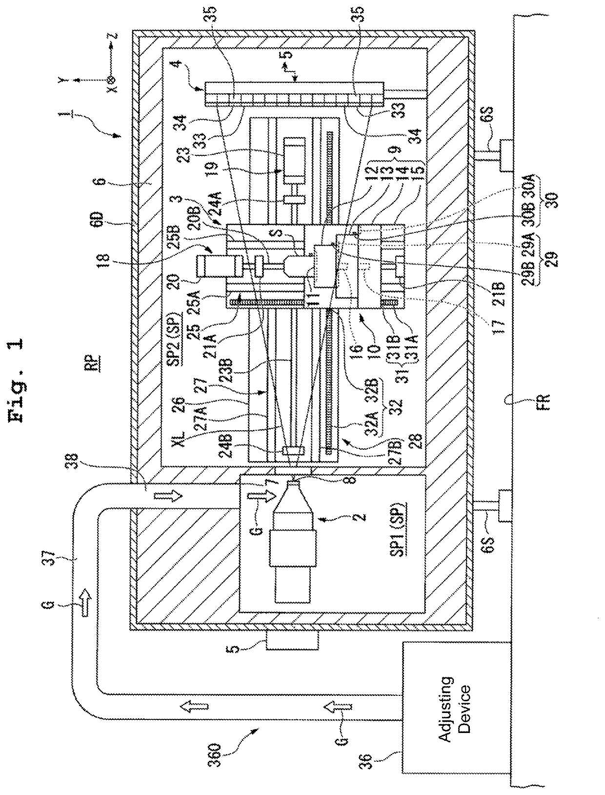
[0037]A first embodiment will be explained. FIG. 1 is a view showing an example of a detection apparatus 1 in accordance with the first embodiment.
[0038]The detection apparatus 1 irradiates a measuring object S with an X-ray XL to detect a transmission X-ray transmitted through the measuring object S. The X-ray is, for example, an electromagnetic wave with a wavelength of approximately 1 pm to 30 nm. The X-ray includes an ultrasoft X-ray with energy of approximately tens of electron volts (eV), a soft X-ray with energy of approximately 0.1 to 2 keV, an X-ray with energy of approximately 2 to 20 keV, and a hard X-ray with energy of approximately 20 to 50 keV.
[0039]In the first embodiment, the detection apparatus 1 includes an X-ray device irradiating the measuring object S with the X-ray and detecting the X-ray having passed through the measuring object S. The detection apparatus 1 includes an X-ray CT inspection device configured to irradiate the measuring object S with the X-ray an...
second embodiment
[0130]Next, a second embodiment will be explained. In the following explanation, the same reference numerals will be assigned to the constitutive parts or components which are the same as or equivalent to those of the first embodiment described above, and the explanations therefor will be simplified or omitted.
[0131]FIG. 6 is a view showing an example of a detection apparatus 1 in accordance with the second embodiment. In FIG. 6, the adjusting system 360 includes the supply port 7 supplying the temperature-controlled gas G to the first space SP1, and a discharge port 43 discharging at least part of the gas in the first space SP1 from the first space SP1. In the second embodiment, the gas discharged from the discharge port 43 includes at least part of the gas G supplied from the supply port 7.
[0132]The chamber member 6 has a duct 44. The duct 44 is formed to link the first space SP1 and the external space RP. The opening at one end of the duct 44 is arranged to face with the first sp...
third embodiment
[0148]Next, a third embodiment will be explained. In the following explanation, the same reference numerals will be assigned to the constitutive parts or components which are the same as or equivalent to those of the embodiments described above, and the explanations therefor will be simplified or omitted.
[0149]FIG. 7 is a view showing part of a detection apparatus 1 in accordance with the third embodiment. Further, in the following explanation, such a case is taken as an example that the supply port 7 is arranged on the +Y side of the X-ray source 2 while the discharge port 43 is arranged on the −Y side of the X-ray source 2. As described above, however, it is possible to arbitrarily determine the number and position of the supply port(s) 7 and the discharge port(s) 43. Further, it is also possible to leave out the discharge port 43.
[0150]In FIG. 7, the detection apparatus 1 includes a temperature sensor 46 detecting the temperature(s) of at least one of the first space SP1 and a me...
PUM
| Property | Measurement | Unit |
|---|---|---|
| Temperature | aaaaa | aaaaa |
| Structure | aaaaa | aaaaa |
| Conduction | aaaaa | aaaaa |
Abstract
Description
Claims
Application Information
 - R&D
- Intellectual Property
- Life Sciences
- Materials
- Tech Scout
- Unparalleled Data Quality
- Higher Quality Content
- 60% Fewer Hallucinations
Browse by: Latest US Patents, China's latest patents, Technical Efficacy Thesaurus, Application Domain, Technology Topic, Popular Technical Reports.
© 2025 PatSnap. All rights reserved.Legal|Privacy policy|Modern Slavery Act Transparency Statement|Sitemap|About US| Contact US: help@patsnap.com