Three-dimensional polymeric medical implants

a medical implant and three-dimensional technology, applied in the field of three-dimensional resorbable polymeric medical implants, can solve the problems of limited ability, difficult control of load-bearing capacity, and unorganized porous structures that suffer from varying pore homogeneity,

Active Publication Date: 2020-07-14
NOVUS SCI
View PDF19 Cites 3 Cited by
  • Summary
  • Abstract
  • Description
  • Claims
  • Application Information

AI Technical Summary

Benefits of technology

[0004]Consequently, there is a need for a three-dimensional resorbable polymeric medical implant having a structure which allows for rapid tissue in-growth in combination with possessing adequate mechanical properties, especially with regard to its ability to withstand compressing forces but still be easily adaptable to underlying tissue structures at the implant site, and whose mechanical properties are predictable, and easily controllable with high enough strengths as required for the specific clinical need. The medical implant should further have a pore homogeneity which is constant throughout the implant structure. Preferably, it should also be possible to provide the medical implant with a specific porosity and at the same time—and more or less independently of the chosen porosity—with a specific bending stiffness (that is, resistance to force applied in a direction perpendicular to the plane of the implant) by combining different materials or by varying the physical shape or morphology within any chosen material.

Problems solved by technology

Three-dimensional implants where the porosity is higher than 70%, and especially those which are based on or contain a foam-like structure, will—even if reinforced with other structures, components or materials—have a limited ability to withstand compressing forces unless the implant in question is made from stiff materials and thus becomes stiff and non-compliant for most or all soft tissue applications.
In unorganized structures such as foams it may also be difficult to control the load-bearing capacity during manufacture of the structures in question.
Unorganized porous structures suffer also from varying pore homogeneity, i.e. the porosity is not necessarily the same for all portions of the unorganized structure.
Further, in unorganized porous structures, properties like porosity, bending stiffness and compression stiffness are usually strongly related to each other, i.e. in practice it may be difficult to produce a medical implant having a desired porosity and, at the same time, a desired bending or compression stiffness.
It is furthermore difficult or impossible to combine different materials and consequently different material properties into a single porous scaffold, which further augment the difficulties and limitations when it comes to design scaffolds with optimal properties for various clinical needs and indications.

Method used


Image

  • Three-dimensional polymeric medical implants
  • Three-dimensional polymeric medical implants
  • Three-dimensional polymeric medical implants

Examples


first embodiment

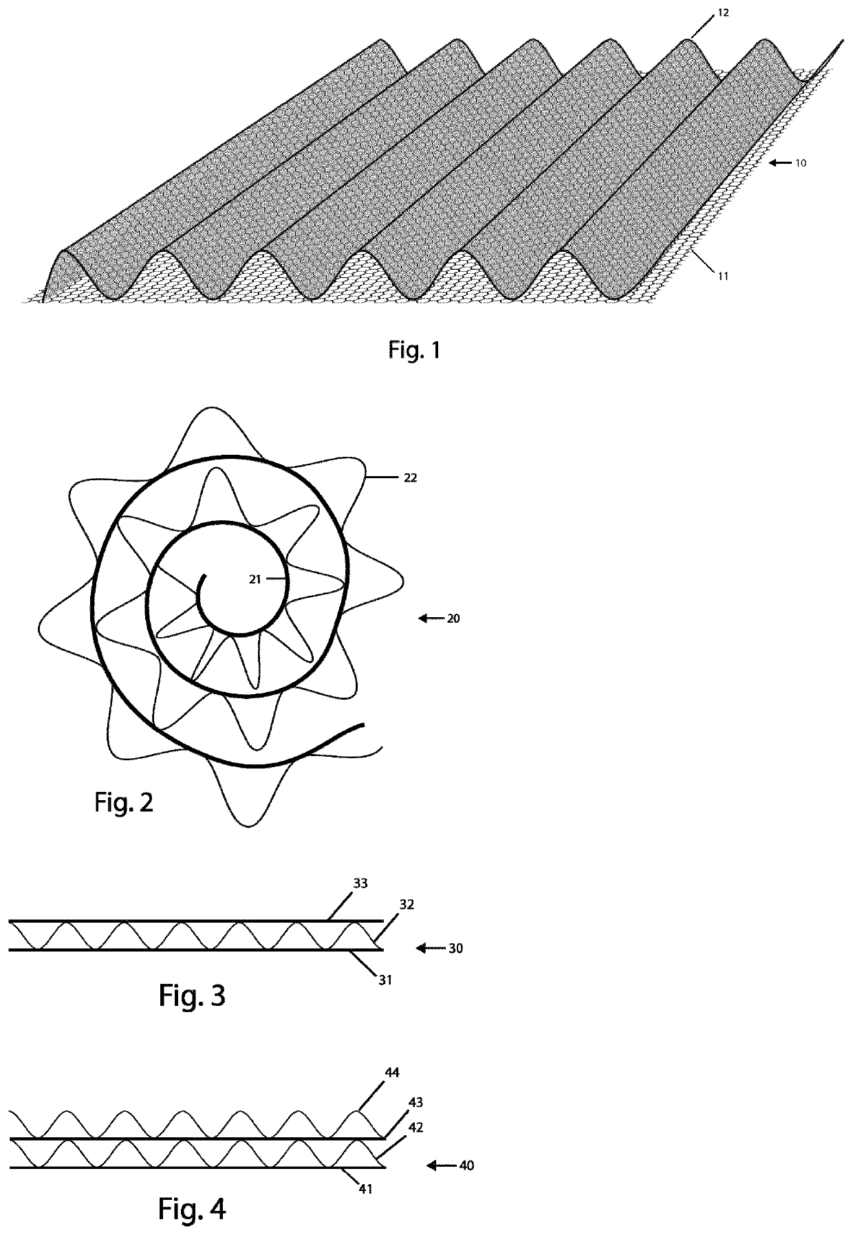
[0020]FIG. 1 illustrates schematically a medical implant 10 according to the present invention. The medical implant 10 comprises a thin porous component 11 and a load-bearing component 12, which in FIG. 1 is arranged on top of the porous component 11 and is connected to the porous component 11. The load-bearing component 12 can be firmly attached, e.g. sewed or tied, to the porous component 11, or be more loosely connected to the porous component 11, e.g. glued or welded, to the porous component 11. The porous component 11 has a limited thickness, approximately 0.02 mm to 1.5 mm thick, and more preferably 0.05 mm to 1.0 mm thick, and can be regarded as a substantially two-dimensional structure and is, for example, arranged as a layer or sheet. Porous components described herein may also be referred to as surface components. The load bearing component 12 is characterized by having both a thickness and a height. The load bearing component 12 is defined as being a flat structure charac...

second embodiment

[0023]In FIG. 2, a medical implant according to the present invention is schematically illustrated in cross-section. Here, a medical implant 20, which essentially has the same features as the medical implant 10 described in conjunction with FIG. 1, comprises a thin porous component 21 and a load-bearing and volume-creating component 22, which is connected to the porous component 21. As illustrated in FIG. 2, the medical implant 20 has been given a rolled configuration, and has the shape of spiral, to thereby create a plug for implantation in abnormal bodily orifices, such as fistulas, but more specifically may be used for endogenous tissue engineering purposes within such areas as rhinoplasty, nipple regeneration after mastectomy, reconstructive surgery for cleft palate, regeneration of bone in clavicle fracture and long-bone fractures in combination with extra support. The spiral configuration of medical implant 20 can be obtained in, for example, an annealing process, or the rolle...

third embodiment

[0024]FIG. 3 shows a cross-sectional view of a medical implant 30 according to the present invention, which comprises a first thin porous component 31, a load-bearing and volume-creating component 32, and a second thin porous component 33. The load-bearing and volume-creating component 32 is positioned between the first porous component 31 and the second porous component 33 in a sandwich structure. As described above, the load-bearing component 32 can be connected to the porous components 31, 33 by e.g. sewing, knitting, gluing or welding, but the triple-layer embodiment shown in FIG. 3 provides for further possibilities in that the load-bearing and volume-creating component 32 can be confined and held in place between the first porous component 31 and the second porous component 33, which are connected to each by e.g. sewing, knitting, gluing or welding. In other words, the load-bearing component 32 can be held in place in a flat bag or pouch created by the porous components 31, 33...


PUM

PropertyMeasurementUnit
porosityaaaaaaaaaa
thickaaaaaaaaaa
thickaaaaaaaaaa

Abstract

The invention relates to a three-dimensional medical implant, comprising a first thin porous component, and a first load-bearing and volume-creating component, which is connected to the first thin porous component; wherein the load-bearing and volume-creating component comprises an organized structure.

Description

FIELD OF THE INVENTION[0001]The present invention relates to a three-dimensional resorbable polymeric medical implant, and particularly to a three-dimensional resorbable polymeric medical implant comprising a first porous surface component, a second porous surface component, and a load-bearing and volume-creating component, which is sandwiched between the first porous surface component and the second porous surface component and which comprises an organized open structure, wherein the organized open structure is a formed two-dimensional structure.BACKGROUND OF THE INVENTION[0002]Three-dimensional medical tissue implants are known. For example, U.S. Pat. No. 5,891,558 to Bell et al. discloses inter alia biopolymer foams as well as biocompatible constructs comprising such biopolymer foams, which can be used in medical implants to replace damaged or diseased tissue, or to provide scaffolds which, when occupied by e.g. host cells, are remodeled to become functional tissue. According to ...

Claims


Application Information

Patent Timeline
Patent Type & Authority Patents(United States)
IPC IPC(8): A61F2/00A61L27/58A61L27/56A61F2/12
CPCA61L27/56A61F2/0077A61L27/58A61F2/12A61F2230/0013A61F2002/0086A61F2230/0023A61F2230/0045
Inventor MATHISEN, TORBJÖRN
Owner NOVUS SCI
Why Eureka
Try Eureka